220 PSPICE tutorial
advertisement
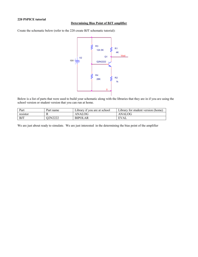
220 PSPICE tutorial Determining Bias Point of BJT amplifier Create the schematic below (refer to the 220 create BJT schematic tutorial): R3 R1 124.5K 4K V2 10V Vout Q1 Q2N2222 R4 R2 28K 1k 0 Below is a list of parts that were used to build your schematic along with the libraries that they are in if you are using the school version or student version that you can run at home. Part resistor BJT Part name R Q2N2222 Library if you are at school ANALOG BIPOLAR Library for student version (home) ANALOG EVAL We are just about ready to simulate. We are just interested in the determining the bias point of the amplifier To simulate: 1) From the main menu pspice->new simulation profile OR you can edit and existing simulation profile from the main menu: pspice->edit simulation profile we will assume that you have selected the later 2) You will then see the menu below 3) You need to choose the analysis type. Choose Bias Point 4) Hit <OK> to close this menu 5) To launch the simulation From the Main menu where you schematic is choose: Pspice-> Run or use the Run PSpice icon on the toolbar on the top of the window with your schematic (blue triangle/arrow) After you simulation a blank waveform window will appear. Close this window. You can display the DC bias points (Voltages and Currents) of your circuit using the icons located at the top of the screen Note they toggle so you can use the same icons to disable display Display bias points on schematic


