Bias Point Simulation
advertisement
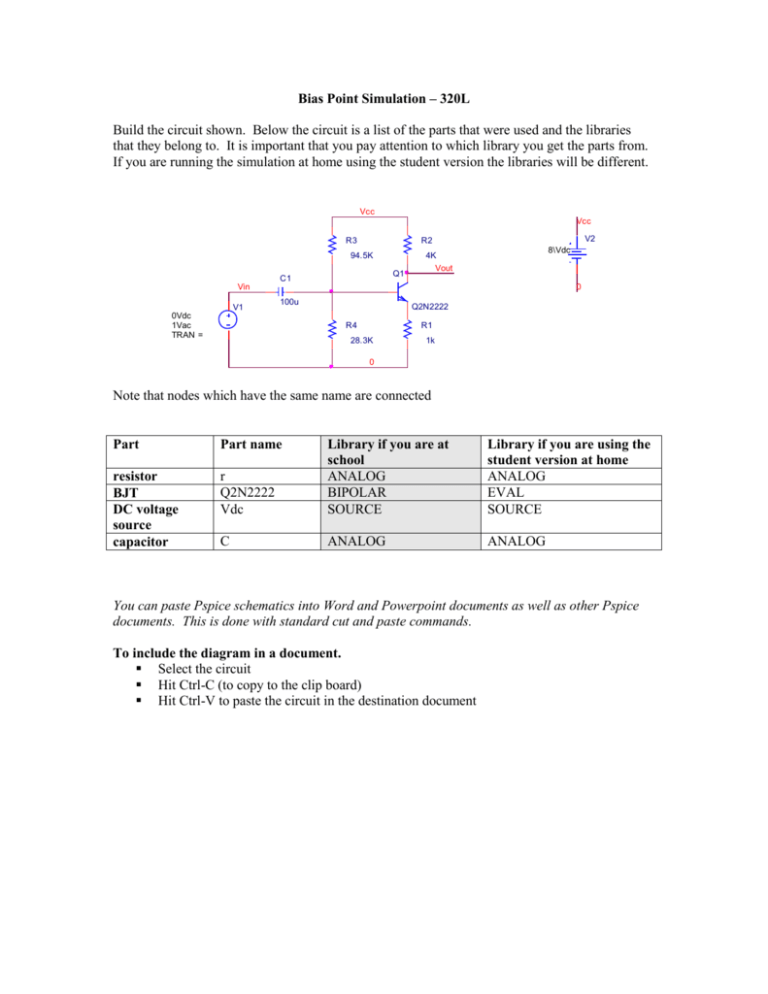
Bias Point Simulation – 320L Build the circuit shown. Below the circuit is a list of the parts that were used and the libraries that they belong to. It is important that you pay attention to which library you get the parts from. If you are running the simulation at home using the student version the libraries will be different. Vcc Vcc R3 V2 R2 94.5K Q1 C1 8\Vdc 4K Vout Vin V1 0 100u 0Vdc 1Vac TRAN = Q2N2222 R4 R1 28.3K 1k 0 Note that nodes which have the same name are connected Part Part name r Q2N2222 Vdc Library if you are at school ANALOG BIPOLAR SOURCE Library if you are using the student version at home ANALOG EVAL SOURCE resistor BJT DC voltage source capacitor C ANALOG ANALOG You can paste Pspice schematics into Word and Powerpoint documents as well as other Pspice documents. This is done with standard cut and paste commands. To include the diagram in a document. Select the circuit Hit Ctrl-C (to copy to the clip board) Hit Ctrl-V to paste the circuit in the destination document Bias point simulations can be sued to determine the Q-point. To perform a bias point simulation From the main menu: Pspice->New Simulation Enter a name for your simulation Hit <create> You will see the menu below Select Bias Point as the Analysis Type Hit <OK> To simulate: from the main menu: Pspice->Run A window will pop-up that is used to display waveforms. It will be empty since you have performed a bias point simulation. Close the window. The toolbar icons shown can be used to toggle the display of bias voltages and currents on the schematic.
