CosmosWorks cylinder with internal temperature
and external convection
(Draft 1, 5/28/06)
Introduction
Consider a thick walled cylinder with a given internal temperature and convection at its external
radius. The analysis of heat transfer in a thick wall infinite cylinder is a one-dimensional problem,
and the analytic solution is known [1]. The cylinder has inner and outer radii of 9.375 and 13.40
inches, respectively, and is made of a material with a thermal conductivity of 1.736e-4 BTU/in-s-F.
The inner and outer temperatures are 500 and 45 degree F, respectively, with and outer convection
coefficient of 2.89e-4 BTU/F-s-in2. The goal is to determine the inner temperature distribution, and
the required heat flow through the wall.
This problem provides a chance to verify ones knowledge of CosmosWorks, and to illustrate some
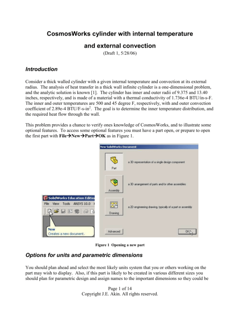
optional features. To access some optional features you must have a part open, or prepare to open
the first part with FileNewPartOK as in Figure 1.
Figure 1 Opening a new part
Options for units and parametric dimensions
You should plan ahead and select the most likely units system that you or others working on the
part may wish to display. Also, if this part is likely to be created in various different sizes you
should plan for parametric design and assign names to the important dimensions so they could be
Page 1 of 14
Copyright J.E. Akin. All rights reserved.
automatically changed later by a design table and/or by the native equation system in SolidWorks.
Create these useful options via:
1. ToolsOptionsDocument Properties tabUnitsIPSOK. While there you can
control the number of decimal places displayed.
2. Next selecting the System Properties tabGeneralShow dimension names give you
the power to set parametric dimensions for future use. These options are shown in Figure 2.
Figure 2 Selecting units and dimension name display
Geometric model
Since the SolidWorks database is three-dimensional you must at least start by defining the region of
interest as a solid. The radial distances are clearly known and provide a starting point for the solid.
As an axially infinite cylinder you can pick an arbitrary slice in the axial direction. Just use a length
that will help keep the element aspect ratios reasonable. Likewise, as with any axisymmetric body,
you simply need to define the planar (radial-axial) shape and rotate it through an arbitrary angle.
Use 5 degrees here for reasonable aspect ratios (if you use a 3-D mesh). Here the area to rotate is
just a rectangle. Draw it true shape in the front plane with:
Page 2 of 14
Copyright J.E. Akin. All rights reserved.
1.
2.
3.
4.
5.
6.
FrontInsert Sketch and use Front or Normal to view if necessary.
Select the two point Rectangle construction (as in Figure 3).
Begin the rectangle relative to the origin (and thus the axis of revolution).
Click and drag out an arbitrary rectangle.
Right click in the graphics area and pick Smart Dimensions.
Select the origin point and the outer radial vertical line and drag the dimension (as initially
sketched) below the part and click to place it there. The sketch dimension appears (here 2.4
inches) along with the current default name (here D1) as seen in Figure 4. The name
appears because of our initial option choice.
Figure 3 Construct the inner and outer radii and vertical height
Figure 4 Sketching and dimensioning the default rectangle
7. To change the dimension value and/or name, double click on that dimension (when you see
the cursor change to the dimension icon). The Dimension panel appears.
8. Since you wish to change both select More Properties in the Dimension panel to get
access to the name as well as the value.
Page 3 of 14
Copyright J.E. Akin. All rights reserved.
9. When the Dimension Properties appears type in the new parametric name (R_outer) and
its actual value (13.4 inches), OK. (See Figure 5)
10. Repeat that process for the inner radius (R_inner and 9.375 inches) and the arbitrary height
(Z_high and 0.5 inches). The results are summarized in Figure 6.
Figure 5 Assigning a name and value to the outer radius of the cylinder
Figure 6 Completing the radial slice dimensions and names
Page 4 of 14
Copyright J.E. Akin. All rights reserved.
Form an axisymmetric body
With the 2D sketch completed it is converted to a #D body by extruding the 2D sketch about the
vertical (Z) axis of the cylinder. If the boundary conditions were not axisymmetric the full (360
degree) body could be formed. But here any slide will do, so a 5 degree segment is randomly
picked to give reasonable element aspect ratios for the dimensions of the 2D sketch:
1. Pick FeaturesRevolved Boss for the current sketch to open the Revolve panel.
2. Insert a vertical centerline at the origin to guide the revolution.
3. In the Revolve panel select the new centerline as the axis. See Figure 7.
4. Enter 5.0 for the angle to revolve through.
5. Optionally, pick Reverse direction so the 3D part will be behind the front plane of the 2D
sketch. That will give a prettier picture when the results are later viewed in the front plane.
Figure 7 Form a wedge segment of the infinite cylinder.
Page 5 of 14
Copyright J.E. Akin. All rights reserved.
Color code boundary surfaces
The required solid body is now finished. At this stage it sometimes helps to assign different colors
to various surfaces of the part. In this example surface colors could remind you of where various
boundary conditions are applied. For example:
1. Assign green for convection at the outer radius. Right click on the outer face.
2. Select FaceAppearanceColor to open the color panel.
3. In the Color panel pick the desire green color, OK. (Top of Figure 8.)
4. Repeat for the inner face and pick red for a known temperature (bottom of Figure 8).
Figure 8 Assigning optional surface colors
Another useful option is being able to turn on (or off) the dimensions of a body or sketch. In the
current view:
1. In the Feature Manager right click on Annotations.
2. Select Show Feature Dimensions.
3. The assigned dimensions appear (Figure 9). If finished reviewing the dimensions repeat the
process and unselect the show option.
Save the part as T_Cylinder_h_body before leaving SolidWorks.
Page 6 of 14
Copyright J.E. Akin. All rights reserved.
Figure 9 Optional display of the segment dimensions
CosmosWorks thermal study
Next, enter CosmosWorks by selecting its managed icon,
. In CosmosWorks:
1. Right click on the Part nameStudy to open the Study panel.
2. Insert a Study name (say FE_T_Cyl_h), select Thermal from the pull down Analysis type
list, and pull down the Mesh type list options. See Figure 10.
3. Any of the three mesh types (solid or two shell options) can be used. For a faster 2D
solution select Shell mesh using mid-surfaces. (At this point a new user will not know
which mid-plane will be selected: an axial slice (yes) or a radial slice.)
Figure 10 Starting a CosmosWorks thermal study
Boundary conditions
The above choice of a Shell mesh using mid-surfaces defines the methods used to apply the
boundary conditions. Since part faces are used to locate the mid-surface, the boundary conditions
must be specified on the faces of the part. By way of comparison, if the alternate shell mesh by
defined surfaces had been selected the boundary conditions would have to be sepecified on the
edges of the faces picked to define the mesh.
Begin the mid-surface mesh boundary conditions with the inner cylindrical (red) face:
1. In the CosmosWorks manager right click on Load/RestraintsTemperature.
2. When the Temperature panel appears right click on the inner face to insert it as the
Selected Entities. (Figure 11, right side)
3. Under Temperature set the units as degrees Fahrenheit and insert a value of 500.
4. Hit Preview (eyeglass icon) to verify your assignment, OK.
Page 7 of 14
Copyright J.E. Akin. All rights reserved.
Figure 11 Specify the known inner cylinder temperature
Next apply the convection conditions of the outer cylindrical (light green) face:
1. In the CosmosWorks manager right click on Load/RestraintsConvection.
2. When the Temperature panel appears rotate the part until you can see the light green face.
3. Right click on the outer face to insert it as the Selected Entities. (Figure 12Figure 11, right
side)
4. Under Convection Parameters select English units, set the temperature to 45 F, and the
surface free convection coefficient (h) to 2.89e-4 BTU/F-s-in2.
5. Preview, OK.
Figure 12 Imposing the outer convection data
Another very useful option is the ability to assign names to any item in the construction tree. This
helps you remember your thought process when you need to come back at a later time to review
your analysis or design. (For legal purposes many engineering designs must be stored for seven
years typically.) In the manager panel:
1. Slow double click on Temperature-1 under Load/Restraint.
2. Enter a descriptive term, say Hot_Inside_T. (See left side of Figure 13.)
Page 8 of 14
Copyright J.E. Akin. All rights reserved.
3. Likewise, change Convection-1 to Convect_H2O.
Figure 13 Assigning user friendly names to restraints
Define the material
The homogeneous (location independent) conducting material is not in the standard materials
library, so its properties must be user defined:
1. In the manager tree, under Mid-surface Shell, right click on the Part nameApply/Edit
Material to open the Material panel.
2. In the Material panel, SourceCustom defined, UnitsEnglish, TypeLinear Elastic
Isotropic (direction independent). See Figure 14.
3. Assign a Material name, say User Defined.
4. In the Thermal conductivity row enter a value of 1.736e-4 BTU/in-s-F. That should be
sufficient for this study. However, CosmosWorks also demands the value of the density in
case you do a transient study. Since the density is unknown enter a fake value, say unity.
Figure 14 Define a conducting material
Here the material property is known to four significant figures. That is high for experimental
material property measurements. To be consistent, the results of the analysis should not be reported
with a larger number of significant digits (although they frequently are).
Page 9 of 14
Copyright J.E. Akin. All rights reserved.
Meshing
For this 1D problem only a few elements are needed in the radial direction. Thus, the default mesh
will be generated:
1. In the manager tree, right click MeshCreate to open the Mesh panel.
2. In the Mesh panel accept the default element size and transition controls, OK. Do not
check “Run study after meshing”. You should always check the mesh first.
3. Visually inspect the mesh, Figure 15, having about 20 elements in the radial direction
should be fine. The solution in the circumferential direction should be constant, so the
number of elements in the second direction should be fine.
4. Save the CosmosWorks files.
Figure 15 The mid-surface, axial section, default mesh
Temperature solution
The thermal analysis is ready for solution. Right click on the Study nameRun. After the
equation solver reports a successful calculation the post-processing results can be reviewed and
plotted.
Page 10 of 14
Copyright J.E. Akin. All rights reserved.
Post processing
Temperatures
Begin the study review by examining the temperature distribution:
1. In the Cosmos manager tree click on Temperature and the double click Plot-1. The
default plot is a continuous color contour.
2. For an alternate format right click in the graphics area and pick Edit Definition.
3. In the Thermal Plot panel pick a Filled, Discrete for the Fringe Type, OK. The contours
appear in Figure 16. Note the convection surface temperature is about 96 F.
Figure 16 Axisymmetric temperature contours
Page 11 of 14
Copyright J.E. Akin. All rights reserved.
Graphs can provide more detail in selected regions:
1. Right click in the graphics window, pick List Selected.
2. Select the bottom edge, click Update to see max, min, and average values.
3. In List Selected panel, pick Plot to open the Edge Plot given in .
Figure 17 Radial temperature graph
The graph agrees very well with the logarithmic analytic solution. A reasonable estimate could
have been obtained with a single element hand solution to help validate the temperature result.
Page 12 of 14
Copyright J.E. Akin. All rights reserved.
Heat flux
The heat flux is a vector quantity obtained from the scalar temperature. In this case it must be in the
radial direction (plot the vector form to see that) so just the values are shown here in Figure 18
Figure 18 Radial heat flux magnitudes
Page 13 of 14
Copyright J.E. Akin. All rights reserved.
Results validation
References
Page 14 of 14
Copyright J.E. Akin. All rights reserved.


