JOURNAL: WOOD SCIENCE AND TECHNOLOGY The influence of
advertisement

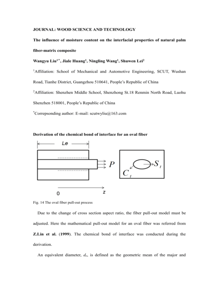
JOURNAL: WOOD SCIENCE AND TECHNOLOGY The influence of moisture content on the interfacial properties of natural palm fiber-matrix composite Wangyu Liu1*, Jiale Huang1, Ningling Wang1, Shuwen Lei2 1 Affiliation: School of Mechanical and Automotive Engineering, SCUT, Wushan Road, Tianhe District, Guangzhou 510641, People’s Republic of China 2 Affiliation: Shenzhen Middle School, Shenzhong St.18 Renmin North Road, Luohu Shenzhen 518001, People’s Republic of China * Correpsonding author: E-mail: scutwyliu@163.com Derivation of the chemical bond of interface for an oval fiber Fig. 14 The oval fiber pull-out process Due to the change of cross section aspect ratio, the fiber pull-out model must be adjusted. Here the mathematical pull-out model for an oval fiber was referred from Z.Lin et al. (1999). The chemical bond of interface was conducted during the derivation. An equivalent diameter, de, is defined as the geometric mean of the major and minor axes a and b (a>b): de ab (14) And de can be used to describe the cross-sectional size of the fiber. The cross section aspect ratio e can be defined as following, e a b (15) And e can be used to depict the shape of the cross section. When e is equal to 1, the fiber shape is standard circular. When e is larger than 1, the fiber shape becomes oval. Using these two parameters, de and e, the cross-sectional shape of the palm fiber can be described. The cross section area St and the perimeter Ct of the oval fiber can be calculated by: de 2 St 4 2 C e 1 d k d e e t 2e (16) in which k e2 1 2e (17) where k is the perimeter ratio of the oval fiber to the circular fiber having the same cross-sectional area. Consider an oval fiber embed in the matrix (Fig. 14). From the required equilibrium condition, we can get f 0 St 0Ct L (18) m0 S m 0Ct L (19) where σf0 and σm0 are the normal stresses in the fiber and matrix at z=0, respectively. St and Ct can be calculated by Eq. 16. τ0 is the frictional stress. L is the length of the debonded zone. If the frictional stress keeps constant during the debonding, we can obtain f (z) f 0 z( f 0 ) L z L m (z) (1 ) m 0 (20) (21) Combine the Eq. 16, 18, 19, 20 and 21, the stress distribution in fiber and matrix can be calculated by f ( z) 4 0 k (L z) de m ( z) (L z) 4 0 kV f d eVm (22) (23) The relative displacement between fiber and matrix is (z) u f (z) u m (z) (24) Therefore d(z) du f (z) du m (z) dz dz dz (25) From the constitutive equation, we have du f (z) dz Ef (26) du m (z) dz Em (27) Therefore the relative displacement is (z) where z Ef 4 0 k (1 ) Lz 2 0 k (1 ) Ef d e Ef d e (28) Ef Vf E mVM (29) Based on the energy-based debonding criterion proposed by Gao et al. (1988), the energy balance equation can be obtained: Pdu f Geo dA dW f dU (30) where P is the axial load, uf is the axial displacement at the free fiber end, GoedA is the energy consumed in the debonded zone, dWf is the energy consumed by friction, dU is the strain energy changing in the system. For the elastic system, we have: 1 ( Pdu f dW f ) 2 dU (31) substitute Eq. 31 to 30 we have: Geo dA 1 ( Pdu f dW f ) 2 (32) where uf can be calculated by: uf L f ( z) Ef 0 dz Vf E f V f EmVm ( Le L) ( Le L) 2 0 kL2 E f (1 ) E f de (33) and Wf can be obtained from: L L2 0 2E f W f kd e 0 ( z )dz kd e 0 ( 4 0 k (1 ) 3 L) 3E f d e (34) Equation 32 was first derived by Z.Lin et al. (1999) in a cylinder fiber model, and it can also be applied for the oval fiber model. From Eq. 33 and 34, duf and dWf can be obtained from: du f E f (1 ) dW f kd e 0 ( L Ef 4 0 kL E f de 4 0 k (1 ) L2 ) E f de (35) (36) The axial load P can be calculated by: P d e2 4 (37) Combined Eq. 32, 35, 36 and 37, we can get: o 8k 0 L(1 ) 16k 2 02 (1 ) 2 8kE f Ge (1 ) 0 de d e2 de 2 (38) Hence, 8kGeo E f (1 ) 4k 0 L(1 ) de de (39) or P kd e 0 L(1 ) kE f 2 d e3Geo (1 ) (40) 2 If η=0 and L=Le, then Pa kd e 0 Le kE f 2 d e3Geo 2 Pb kE f 2 d e3Geo 2 (41) where Le is the embedded length of fiber. Therefore, Goe can be obtained from Geo 2( Pa Pb ) 2 2 P2 kE f 2 d e3 kE f 2 d e3 This is the derivation of Eq. 4 in the main text. (42)


