Instruction Manual
Manual No. 012-08101
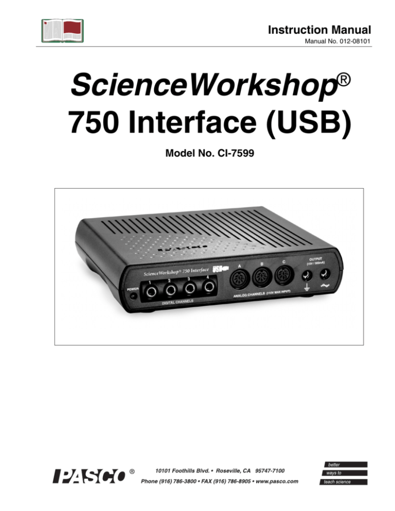
ScienceWorkshop
750 Interface (USB)
®
Model No. CI-7599
750 Interface (USB)
Model No. CI-7599
Table of Contents
Equipment List........................................................... 3
Introduction ............................................................. 4
Computer Requirements for Using the Interface ..................... 4
Operation and Setup Procedures....................................... 5
A. Operation Requirements and Precautions .................................................................................5
B. Connecting the Interface to Your Computer .............................................................................5
C. Plugging a Sensor into the Interface..........................................................................................6
D. Using the Interface with DataStudio Software..........................................................................6
E. Changing Interfaces Between Experiments...............................................................................6
Using the Interface as a Signal Generator ........................... 7
Operating the Interface with a Power Amplifier ..................... 8
A. Setup the CI-6552A Power Amplifier with the Interface .........................................................8
B. Generate Signals from within DataStudio.................................................................................8
C. View the Amplified Signals in DataStudio ...............................................................................9
D. View the Voltage or Current in DataStudio ..............................................................................9
Troubleshooting ....................................................... 10
Appendix A: Specifications........................................ 11-12
Appendix B: Electromagnetic Compliance ............................. 13
Appendix C: Frequently Asked Questions ........................ 14-16
Appendix D: Theory of Operation ................................ 17-19
Flash Memory ..............................................................................................................................17
Analog Input Channels.................................................................................................................17
Digital Input/Output Channels .....................................................................................................18
Sampling Rate ..............................................................................................................................18
Built-In Function Generator-Amplifier........................................................................................19
Accessing Analog Output ............................................................................................................19
Digital Event Sampling ................................................................................................................19
Appendix E: Technical Support ....................................... 20
Appendix F: Copyright and Warranty Information .................. 21
2
®
Model No. CI-7599
ScienceWorkshop®
ScienceWorkshop®
750 Interface (USB)
Model No. CI-7599
Equipment List
Power Switch on
back panel
1
2
Power
Digital
Indicator Channels
Signal
Generator
Analog
Channels
3
Included Equipment
1. ScienceWorkshop® 750 USB Interface box (1)
2. AC Adapter, 12 VDC, 60 Hz, 40 W (1)
3. USB cable (1)
Replacement
Model Number*
CI-7599
540-034 or 540-035
514-016
*Use Replacement Model Numbers to expedite replacement orders.
Additional Equipment Required
USB-compatible computer
Any PASCO ScienceWorkshop® Sensor
DataStudio software, version 1.7 or later
A sensor with a
CI-prefix*
CI-6870D or
CI-6871D
* Either an analog or digital ScienceWorkshop® sensor is required for real-time data
collection. Any photogate or photogate set beginning with the prefix “ME” can also
be used with the interface.
®
3
750 Interface (USB)
Model No. CI-7599
Introduction
The PASCO 750 USB Interface, is a USB (Universal Serial Bus) data
acquisition interface designed for use with any of PASCO’s
ScienceWorkshop® Sensors. The 750 USB operates exactly the same
as the 750 SCSI interface. The only functional difference between the
750 USB and SCSI interfaces is that the 750 USB plugs into a USB
port on the back of your computer (the 750 SCSI interface interface
connects to a SCSI port or RS-232 port). Users just plug the sensor
into the interface, perform the necessary setup in DataStudio, and can
immediately begin collecting data.
The PASCO 750 USB interface is designed for use with DataStudio,
version 1.7 or later. The 750 USB interface is another option for
customers who have computers with USB hardware (instead of older
computers with SCSI cards and connectors) and want to use USB
interfaces and connections.
Note: The 750 USB interface is compatible with PASCO
ScienceWorkshop sensors. The 750 USB will not work with
PASPORT™sensors. Those customers wishing to use PASPORT
products and sensors with DataStudio need to purchase USB Links or
PASPORT Xplorers.
Computer Requirements for Using the
Interface
Windows®-Based Computers: Pentium Processor with one or more
USB ports, and Windows 98, ME, 2000, or XP. [The interface cannot
be used with Windows 3.1, 95, or NT 4.0 ].
Macintosh® Computers: PowerPC processor with one or more USB
ports, and OS 8.6 or higher
4
®
Model No. CI-7599
750 Interface (USB)
General Operation Requirements and Setup
A. Operation Requirements and Precautions
a) The interface must be used with PASCO’s DataStudio software and
ScienceWorkshop sensors. The interface will not work with PASPORT
sensors or other sensors, software, or interface (i.e. Xplorer, etc.)
Also, you can use only one 750 USB interface per computer.
b) A power supply and USB cable are required for operation. Always
plug the power supply into a standard three-pronged, grounded wall
outlet.
Note: For more information about operational requirements, see
Appendix C, ”Frequently
Asked Questions” in this
manaul.
WARNING: The interface is not water-proof. To avoid the risk
of shock, keep the interface, AC adapter, and cable away from water
and liquids. If conducting an experiment with liquids or water, place
the liquid container at least one foot away from the interface. For
maximum protection, keep liquids in closed containers with covers.
Also during operation, do not block the ventilating louvres on the top
of the interface box. The louvres help prevent the interface from
overheating during prolonged use.
B. Connecting the Interface to Your Computer
1. Install DataStudio (version 1.7 or later) on your computer.
2. Connect one end of the USB cable to the USB port on the back of
your computer.
3. Connect the other end of the USB cable to the USB port on the back
of the interface.
To locate a USB port,
look for the USB symbol.
4. Connect the power supply to the jack on the back of your interface
box and to a grounded wall outlet.
5. On the back of the interface, turn the power switch to the “1” (on
position). When the green power light illuminates, the power is
turned on.
®
5
750 Interface (USB)
Model No. CI-7599
C. Plugging a Sensor into the Interface
Analog sensors have DIN
connectors and plug into channels
A, B, and C on the interface.
Digital sensors have stereo plugs
and insert into channels 1, 2, 3, and
4 on the interface.
C
Figure 1: Connecting a
Sensor to the Interface
D. Using the Interface with DataStudio Software
Note: Before using the interface with DataStudio software, you must
have DataStudio (version 1.7 or later) loaded onto your computer, the
interface connected to your computer, and the power supply turned on.
1. Connect a ScienceWorkshop sensor to any channel on the interface.
2. Open DataStudio and double click “Create Experiment.”
3. In the Sensors list, double-click
the sensor to associate the
sensor with the interface
channel (See Figure 2) in the
setup window.
4. In the Displays list, doubleclick on any of the displays to
open a display.
Note: Both the 750 USB
Interface and 750 SCSI
interface use the same
setup window in DataStudio. For more information on operating the
interface with DataStudio, see Appendix C,
“Frequently Asked Questions” in this manual or
the DataStudio online
help (ver. 1.7 or later).
Figure 2: Associating the Sensor
icon with the Interface Channel
5. To collect some data, click the Start button on the main toolbar.
Result: Data appears in real-time in the display.
6. To stop collecting data, go to the main toolbar and click the Stop
button.
E. Changing Interfaces Between Experiments
If you have both the 750 USB interface and another type of interface
connected to your computer simultaneously, you cannot use both
simultaneously in DataStudio. To change interfaces in DataStudio,
click the Change button in the Experiment Setup window, select the
desired interface, and click OK.
6
®
Model No. CI-7599
750 Interface (USB)
Using the Interface as a Signal Generator
(no amplifier required):
The 750 USB interface contains a built-in function generator for
creating up to eight types of waveforms (sine, square, triangle,
sawtooth, ramp up, ramp down, positive ramp up, positive ramp down,
as well as DC voltages.) when the interface is used with DataStudio.
No power amplifier is required for signal generation. The computer is
used as an AC signal generator to power external circuits while it
monitors its own output current as well as other inputs. Using the 750
interface, DataStudio can create an analog signal that ranges in
frequency from DC to 50 KHz, with an amplitude of +/- 5 volts, and
with a current of up to +/- 300mA. For specific frequency, range, and
amplitude limits, see Appendices A (Specifications) and C (subsection
“Built-In Function Generator/Amplifier”) in this manual.
To use the Interface as a Signal Generator for a Circuit (or
Other Device):
1. Insert a banana plug into the Ground port (
Note: Using DataStudio,
you can also generate
waves without a Power
Amplifier connected to
the interface. See “Using
the Interface as a Signal
Generator” in this manual.
) on the interface, and
connect the ground lead to the ground on the circuit board (or other
device).
) and
2. Insert a banana plug into the Signal Generator port (
connect the lead to the positive lead on the circuit board (or other
device).
3. Below the Sensors list, click on the Signal Generator icon to open
the Signal Generator dialog box.
4. In DataStudio, use the Signal Generator dialog box to choose the
type of wave, and control the amplitude, frequency, and voltage
output.
5. To create signals, click the Start button.
®
7
750 Interface (USB)
Model No. CI-7599
Operating the Interface with a Power
Amplifier
With a PASCO CI-6552A Power Amplifier II plugged into an analog
channel of the ScienceWorkshop 750 USB interface, you can supply up
to 1 A of external current at +/- 10 volts.
WARNING: To prevent power surges, always turn on the
Power Amplifier before running DataStudio. Turning on the amplifier
while DataStudio is opening may cause a power surge, resulting in
damage to your computer.
To use the output of the Power Amplifier II, connect the load to the
banana jacks on the front of the Power Amplifier II. There is a power
switch on the back left hand corner of the Power Amplifier II.
When the Power Amplifier II is operating, a green power indicator
light on the front panel illuminates. A red current overload light comes
on whenever the maximum current of 1A is exceeded. If this warning
light is on, the waveform is distorted and you should reduce the output
voltage.
A. Set up the CI-6552A Power Amplifier with the Interface
1. Plug the DIN connector of a Power Amplifier into any analog channel
on the 750 ScienceWorkshop interface.
2. Open DataStudio.
3. In the Experiment Setup window, click on the Power Amplifier icon
in the Sensor list and drag it to any channel on the picture of the
interface. Result: A Power Amplifier icon with a Signal Generator
icon attached displays on the interface.
B. Generate Signals from within DataStudio (with the Power
Amplifer Connected)
1. In DataStudio’s Signal Generator
dialog, select an AC waveform.
2. Adjust the amplitude and
frequency with the plus (+) and
minus (-) buttons (Figure 3) or
type in a numerical value. Use the
arrows for stepped progression.
8
Figure 3: Signal Generator
dialog in DataStudio
®
Model No. CI-7599
750 Interface (USB)
3. To generate signals, click the Start button.
For more information about signal generation, see the DataStudio
online help.
C. View the Amplified Signals in DataStudio
From the Data list, drag the Output Voltage icon to a display (i.e.
Graph, Scope, etc.), and click the Start button.
D. View the Voltage or Current in DataStudio
1. In the setup window, double click the Power Amplifier icon.
2. When the Sensor Properties dialog box opens, click on the
Measurement tab. In the Measurement dialog box, check the
Voltage and/or Current box.
3. To view the voltage: In the Data list, drag the Voltage icon to an
open display (i.e. Graph, Digits, etc.).
Or
To view the current: In the Data list, drag the Current icon to an
open display(i.e. Graph, Digits, etc.).
®
9
750 Interface (USB)
Model No. CI-7599
Troubleshooting
Problem
Recommendations
The interface does
not turn on.
Ensure you have the power supply connected to the interface
and a grounded outlet. Check to see that the power switch is
turned on in the back of the interface. Ensure that the USB
cable is inserted properly to both the interface and to the back of
your computer.
My computer’s
operating system
does not recognize
the interface and
asks for a driver.
You must have DataStudio version 1.7 software loaded onto your
computer. DataStudio 1.7 and later versions include a driver (set
of software instructions) that allow your computer to
communicate with the 750 USB interface. If you have an earlier
version of DataStudio installed, your computer will not recognize
the interface. Check “Computer Requirements” in this manual to
ensure your operating system is compatible with USB devices.
If you have DataStudio 1.7 installed and you still receive device
error messages, contact PASCO’s Technical Support Dept. (1800-772-8700) or 916-786-3800.
10
DataStudio does
not allow me to
collect data with
the interface
connected.
Recheck the USB cable and power connections. Also, check to
ensure you have opened the proper setup window in
DataStudio. In the Experiment Setup window, click the Change
button and select “SW750” in the Please Choose a Data
Source” box. When you click OK, the correct setup window
opens.
I want to collect
data with both a
750 USB interface
and a PASPORT
interface
simultaneously.
DataStudio does not allow you to collect data from multiple
ScienceWorkshop interfaces or PASPORT and
ScienceWorkshop interfaces simultaneously. Instead, use the
Change button in DataStudio’s Experiment Setup window to
alternate between interfaces.
I want to switch
between the 750
USB and 750 SCSI
interface in
DataStudio.
Both the 750 (USB) and 750 (SCSI) ScienceWorkshop
interfaces use the same Experiment Setup window in
DataStudio. When you have the 750 USB interface connected,
you will see a “USB” designator in the setup window header.
Instead, use the Change button in DataStudio’s Experiment
Setup window to alternate between interfaces.
I am unable to
operate the Power
Amplifier with the
interface.
Check to ensure you have connected the Power Amplifier to
analog channel A,B, or C on the interface. Both devices must be
turned on. Also, ensure you have associated the Power
Amplifier icon on the same channel in DataStudio’s Experiment
Setup window. For more information, see DataStudio’s online
help.
®
Model No. CI-7599
750 Interface (USB)
Appendix A: Specifications
USB 750 Interface
Description
Power:
12 VDC to 20 VDC at 2 A, 2.1 mm jack
Computer Connection:
Universal Serial Bus (USB), 12 Mbps maximum
data transfer rate
Digital Channels:
• 4 input/output channels
• TTL compatible input/output levels with 8 mA
maximum drive current
• Maximum input logic transition time: 500 ns
• Electrostatic Discharge (ESD) protected inputs,
assuming the human body model standard, MilStd-3015.7
• Digital input: Edge sensitive and sampled at 10
KHz (100 µs), (1 µS resolution for the Motion
Sensor)
Analog Channels:
• 3 identical channels with differential inputs and 1
M ohm impedance
• +/- 10 V maximum usable input voltage range (+/12 V absolute maximum input voltage range)
• ESD-protected input similar to that of the digital
channels
• 3 voltage gain settings on each analog channel
(1,10, and 100)
• Small signal bandwidth up to the ADC: 1 MHz for
a gain of 1, 800 KHz for a gain of 10, and 120 KHz
for a gain of 100; input amplifier slew rate: 1.2 V/
µs (The actual bandwidth is determined by the
sampling rate of the ADC).
Analog-to Digital Conversion:
• 5 input sources for the 12-bit ADC: channels A-C,
signal generator analog output voltage and current
• Voltage resolution at the ADC input: 4.88 mV
(0.488 mV at a gain of 10; 0.049 mV at a gain of
100)
• Current measurement resolution: 244 µA, where
each volt measured represents 50 mA
• Offset voltage accuracy < +/- 3 mV (For measuring
full-scale voltages (or 1 V with a gain of 10, etc.),
the total error will be less than +/- 15 mV,
accounting for the gain error in the input amplifier.
• Sample rate range: once every 3600 seconds 250 KHz (The conversion time between
consecutive channels in a burst is 2.9 µs)
• 8x oversampling for improved accuracy for sample
rates <100 Hz.
®
11
750 Interface (USB)
Model No. CI-7599
Appendix A - Specifications (Continued)
USB 750 Interface
Analog Output:
12
Description
• DC value ranges: -4.9976 V to + 5.0000 V in steps of 2.44
mV
• Accuracy at the DIN connector: (+/- 3.6 mV +/- 0.1% full
scale)
• Peak-to-Peak amplitude adjustment ranges for the AC
waveform: 0 V to +/- 5 V in steps of 2.44 mV
• AC waveform frequency ranges: 1 mHz (0.001 Hz) - 50
KHz, +/- 0.01%
• Maximum amplified output at the banana jacks: about 300
mA at +/- 5 V, current limited at 300 mA +/- 12 mA
®
Model No. CI-7599
750 Interface (USB)
Appendix B: Electromagnetic Compliance
Note: This equipment has been tested and found to comply with the
limits for a Class A digital device, pursuant to part 15 of the FCC
Rules. These limits are designed to provide reasonable protection
against harmful interference when the equipment is operated in a
commercial environment. This equipment generates, uses, and can
radiate radio frequency energy and, if not installed and used in
accordance with the instruction manual, may cause harmful
interference to radio communications. Operation of this equipment in a
residential area is likely to cause harmful interference, in which case
the user will be required to correct the interference at his own expense.
The PASCO Model CI-7599 750 ScienceWorkshop Computer Interface
has been tested and complies with the essential protection
requirements of Council Directive 89/336/EEC on the approximation
of the laws of the Member States relating to electromagnetic
compatibility. Assessment of compliance of the product with the
requirements relating to electromagnetic compatibility was based on
the following Directives and Standards:
• EN 50081-1 Electromagnetic compatibility generic emission
standard
• EN 55022, CISPR 22 Class A Limits and methods of measurements
of radio interference characteristics of information technology
equipment.
• EN 50082-1 Electromagnetic compatibility generic immunity
standard.
• IEC 801-2 Electrostatic discharge requirements
• IEC 801-3 Radiated electromagnetic field requirements
• IEC 801-4 Electrical fast transient/burst
®
13
750 Interface (USB)
Model No. CI-7599
Appendix C: Freq uently Asked Questions
What is the 750 USB Interface?
The 750 USB interface was developed to meet the needs of those users
who prefer the USB connection (or those whose computers do not
support SCSI connections).
The PASCO 750 SCSI interface uses a SCSI (Small Computer System
Interface) port to communicate with the PC or MacIntosh (Mac)
computer to which it is connected. The SCSI-equipped interface is
now known as the “750 SCSI interface.”
Are there other differences between the 750 SCSI and the 750
USB?
No. The 750 USB is identical to the 750 SCSI in all respects, except
for the communications port. The 750 USB uses all the same sensors
and performs the same functions as the 750 SCSI. The overall rate at
which data is transmitted to the Mac or PC is essentially the same. The
750 USB Interface only works with DataStudio software; this differs
from the 750 SCSI interface, which is compatible with the older
ScienceWorkshop software.
How do I know if my computer has a USB port or a SCSI port?
If your computer has a USB port, you will see the USB symbol
embossed, engraved, or printed next to the port on the back of your
computer. If you purchased a computer that was manufactured in 2001
or 2002, chances are you have a USB-compatible computer.
A SCSI port works with a serial 50-pin connector cable and often
requires a SCSI card.
If you are still unsure about the type of port your computer has, check
the documentation that came with your computer or call the
manufacturer.
My computer has two USB ports. Can I connect and use two 750
USB Interfaces at the same time?
You can connect two 750 USB Interfaces, but only one interface will
be recognized by DataStudio. The interface that is recognized first will
14
®
Model No. CI-7599
750 Interface (USB)
operate normally. There is no way to switch between the two 750
interfaces in DataStudio.
Is the 750 USB Interface compatible with PASCO’s new
PASPORT line of sensors?
No. The 750 USB is compatible with PASCO’s line of “CI” sensors,
which includes over 40 different sensor types.
Does the 750 USB Interface work with ScienceWorkshop
software?
No. ScienceWorkshop software, which is available at no charge from
PASCO, and works with all other PASCO interfaces (including the 750
SCSI), does not recognize the USB connections that come with newer
computers and operating systems. DataStudio Lite, which is also
available free from PASCO, supports all PASCO interfaces including
the 750 USB.
I have a computer with USB connections. Does it matter whether
I purchase the 750 SCSI or 750 USB?
Not really. The 750 USB will usually result in lower system cost,
since a separate SCSI interface card is usually required for most
systems using the 750 SCSI. Also, installation of the SCSI card within
the computer and system configuration is more involved than the
simple “Plug and Play” operation of USB. For newer computers and
operating systems that support USB, the 750 USB interface is
preferred.
I have an older computer that doesn’t have USB. Is there any
way I can still use the 750 USB Interface?
If you have a PC that is running Windows 98, 2000, ME, or XP (in
other words, any system NOT running Windows 3.1, 95, or NT4), you
can use the 750 USB as long as the required USB port can be installed
in the computer. USB ports can be purchased from many electronic
stores at low cost.
You can also upgrade some olders Macs with USB ports if it is a
PowerPC Mac with a PCI/PCMCIA bus running Mac OS v. 8.6 or
better.
®
15
750 Interface (USB)
Model No. CI-7599
Does the 750 USB have a serial connection like the 750 SCSI?
No. The 750 USB Interface can connect to the computer only with the
USB port.
If I have a 750 USB and a PASPORT Xplorer connected at the
same time, which would be recognized first and have priority?
The interface you choose first in DataStudio is the one that has the
priority. If you select the PASPORT data source in DataStudio (using
the Please Choose Data Source box that appears when you click the
Change button), DataStudio will connect to the Xplorer. If you select
the 750 data source, DataStudio will connect to the 750. If the Xplorer
has logged data runs, or it has a sensor plugged in, the PASPORTAL
window will automatically launch DataStudio with the PASPORT data
source selected.
Figure 4: Data Source Window
16
®
Model No. CI-7599
750 Interface (USB)
Appendix D: Theory of Operation
Flash Memory
The 750 stores its operating system software and waveform patterns in
flash memory. After turning on the power supply, the interface
initializes the operating system without requiring user initiation in
DataStudio. When a new revision of DataStudio is later loaded onto
one’s computer, the interface automatically upgrades the system
software and waveforms in flash memory.
Analog Input Channels
All three analog input channels (A,B, and C) on the 750 interface are
identical. Each has differential inputs; in other words, they are like the
inputs to a voltmeter where neither lead is connected to ground. The
voltage measured is the voltage difference between the inputs.
Each channel has three software accessible gain settings: 1, 10, and
100. When an analog sensor is plugged into the interface, the signal is
applied to a device called a differential amplifier. As the name
suggests, a differential amplifier amplifies the difference between two
signals.
In this case, the output of the amplifer is the difference between the
A+ input and the A- input, multiplied by a fixed gain that is selectable
in DataStudio software at 1, 10 or 100. From this point, each analog
signal (A, B, and C plus other internally-generated signals) is applied
to a device called a multiplexer. The multiplexer, which acts like a
switch, selects which input channel is to undergo analog-to-digital
conversion.
There are other analog channels within the 750 interface. Two
channels are dedicated to voltage and current measurements for the
Function Generator, plus others for internal diagnostic purposes.
Channels to be converted are selected by the 750 interface under the
control of DataStudio. The analog-to-digital converter uses 12-bit
conversion, so the maximum range of each analog input, +/- 10 volts
can be converted to a range of digital numbers from 0 to 4095 (2^12).
When the analog value is in digital form, it can be sent immediately to
the host computer for further processing, or stored temporarily with the
750 interface internal memory.
®
17
750 Interface (USB)
Model No. CI-7599
Digital Input/Output Channels
When a digital sensor plugged into one or more of the 750 interface,
the interface may perform several different tasks, with the task
dependent on the type of sensor connected. It may time the interval
between external events (i.e. a photogate), count external events (i.e. a
nuclear sensor), or it may both trigger an external event and perform a
timing function ( i.e. Motion Sensor). When you choose a particular
digital sensor in DataStudio, information is transmitted to the 750
inteface, and the microprocessor within the interface knows what to do
and when, and on which channel. The timing function is carried out
within specialized digital devices within the 750 interface, called Field
Programmable Gate Arrays. These devices are programmed to
perform many digial functions and perform them at very high speeds.
Sampling Rate
The maximum samples rate depends on the channels the user selects
for measurement. For higher sample rates, the interface samples a
block of 2000 bytes and then transfers the block. Once transfer of
bytes to the host begins, the interface starts sampling a new block.
This is called burst mode, since there is a small time interval when data
is not being sampled. The main use of this mode is for the virtual
oscilloscope. Table 1 shows the sampling constraints while using a
fast computer to record the data.
Table 1: Sample Rate Constraints
Sample
Rate
No. of Channels
Comment
250 KHz
1 analog
Burst mode
100 KHz
3 analog
Burst mode
50 KHz
5 analog
Burst mode
20 KHz
1 or 5 analog
Continuous* (burst)
10 KHz
1 analog + 1 digital or
5 analog
Continuous* (Burst)
< 100 Hz
5 analog
Continous 8x oversample
(improved accuracy at < 100
Hz)
18
®
Model No. CI-7599
750 Interface (USB)
* Continuous sampling with 5 channels selected is not possible to
sustain for more than a few seconds.
There are five analog channels from which to choose: channels A-C,
analog output voltage (at banana jacks), and the analog output current.
Please note that for continuous sampling, the speed of the computer
may slow down, especially if the interface is busy processing with
many displays open in DataStudio.
Note: The sampling rate does not depend on the number of digital
channels selected in DataStudio, as they are sampled separately and
simultaneously at 10 KHz.
Built-In Function Generator/Amplifier
The USB 750 has a built-in function generator that is used to output
analog signals. These can be either AC signals, such as sine and
triangle waveforms, or a DC signal, ranging between +/- 5 volts. For
the AC waveforms, of which there are eight waveforms resident in
Flash, the frequency can range from 1 mHz (0.001 Hz) to 50 KHz and
the peak-to-peak amplitude can be adjusted from 0 V to +/- 5 V with
increments of 2.44 mV. The output voltage is calibrated at the factory
to null the offset voltage and set the full scale voltage.
Accessing Analog Output
There are two different methods of accessing the analog output signal.
The first is to connect the test leads to the 750 interface output banana
jacks. The output current can be monitored along with the output
voltage. The second is to use a CI-6552A Power Amplifier (which has
a voltage gain of 2 and delivers 10 W) and connect its DIN plug to one
of the analog channels, A-C.
Digital Event Sampling
The 750 can sample digital events for photogate timing. The 750 uses
hardware edge detection so that it can capture either edge or both as
events, a feature useful for setting trigger conditions. It can count
digital events from devices, such as a Geiger tube or a Rotary Motion
Sensor. Each channel has an independent 16-bit counter. For motion
sensing, either single or dual, the internal counters and edge detectors
provide improved performance with less noise in the measurement.
®
19
750 Interface (USB)
Model No. CI-7599
Appendix E: Technical Support
For assistance with the CI-7599 750 USB Interface or any other
PASCO products, contact PASCO as follows:
Address: PASCO scientific
10101 Foothills Blvd.
Roseville, CA 95747-7100
Phone: (916) 786-3800
20
FAX:
(916) 786-3292
Web:
www.pasco.com
Email:
techsupp@pasco.com
®
Model No. CI-7599
750 Interface (USB)
Appendix F: Copyright and Warranty
Information
Copyright Notice
The PASCO scientific 012-08101A ScienceWorkshop 750 Interface
(USB) Manual is copyrighted and all rights reserved. However,
permission is granted to non-profit educational institutions for
reproduction, of any part of the 012-08101A ScienceWorkshop 750
Interface (USB) Manual, providing the reproductions are used only for
their laboratories and are not sold for profit. Reproduction under any
other circumanstances, without the written consent of PASCO
scientific, is prohibited.
Limited Warranty
PASCO scientific warrants the product to be free from defects in
materials and workmanship for a period of one year from the date of
shipment to the customer. PASCO will repair, or replace, at its
opetion, any part of the product which is deemed to be defective in
material or workmanship. The warranty does not cover damage to the
product caused by abuse or improper use. Determination of whether a
product failure is the result of a manufacturing defect or improper use
by the customer shall be made solely by PASCO scientific.
Responsibility for the return of equipment for warranty repair belongs
to the customer. Equipment must be properly packed to prevent
damage and shipped postage or freight prepaid. (Damage caused by
improper packing of the equipment for return shipment will not be
covered by the warranty.) Shipping costs for returning the equipment
after repair will be paid by PASCO scientific.
®
21


