Lab 9
advertisement
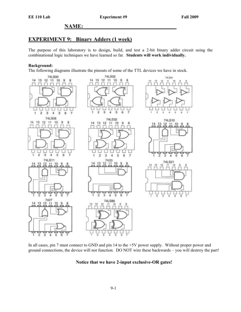
EE 110 Lab Experiment #9 Fall 2009 NAME: _________________________________ EXPERIMENT 9: Binary Adders (1 week) The purpose of this laboratory is to design, build, and test a 2-bit binary adder circuit using the combinational logic techniques we have learned so far. Students will work individually. Background: The following diagrams illustrate the pinouts of some of the TTL devices we have in stock. In all cases, pin 7 must connect to GND and pin 14 to the +5V power supply. Without proper power and ground connections, the device will not function. DO NOT wire these backwards – you will destroy the part! Notice that we have 2-input exclusive-OR gates! 9-1 EE 110 Lab Experiment #9 Fall 2009 We recently discussed the half adder and full adder in class. Here are their essentials once again. A two-bit adder can be constructed from the half adder and full adder in the following way. Here, X and Y are two-bit binary numbers. Their sum is Z, with a carry-out of C1. Procedure: 1) Design a logic circuit to realize the half adder. (Minimizing your design is strongly advised. It will help you complete the construction and testing process more rapidly.) Show your work below, including K-map, Boolean equations, and logic diagram. Include part numbers and pinouts. 9-2 EE 110 Lab Experiment #9 Fall 2009 2) Design a logic circuit to realize the full adder. Show your work below, including K-map, Boolean equations, and logic diagram. Include part numbers and pinouts. 3) Next, build your half adder and full adder circuits. Test these circuits individually to make sure they function according to the specified truth tables. Use switches as inputs and LEDs as outputs. 4) Draw a single schematic below that shows your half adder, full adder, and their interconnections to realize the two-bit adder specified previously. 9-3 EE 110 Lab Experiment #9 Fall 2009 5) Alter your breadboard realization to implement the two-bit adder according to your schematic in part 4. Use switches to input each binary operand and the 7-segment LED display to indicate the sum (including the carry-out bit). 6) Complete the truth table below to fully describe the observed behavior of your two-bit binary adder. X1 X0 Y1 Y0 Operatio n 0 0 0 0 0 0 0 0 1 1 1 1 1 1 1 1 0 0 0 0 1 1 1 1 0 0 0 0 1 1 1 1 0 0 1 1 0 0 1 1 0 0 1 1 0 0 1 1 0 1 0 1 0 1 0 1 0 1 0 1 0 1 0 1 0+0 0+1 0+2 0+3 1+0 1+1 1+2 1+3 2+0 2+1 2+2 2+3 3+0 3+1 3+2 3+3 Require d Sum 0 1 2 3 1 2 3 4 2 3 4 5 3 4 5 6 Observe d Sum 7) Demonstrate the operation of your logic circuit to the teaching assistant or professor. Get their signature and comments regarding the functionality of your circuits. TA Signature: _______________________________________________________________ 8) Refer to your schematic in step 4. Let’s assume each gate has a propagation delay of units of time. What is the maximum number of gate delays possible from input to output in your design? 9-4 EE 110 Lab Experiment #9 Fall 2009 9) Draw a concise diagram illustrating this worst-case delay path, showing the input(s), output(s), and gates involved. 10) Complete the following: a. What results did you obtain in this experiment? b. What difficulties did you have? c. What are your conclusions? What did you learn about binary adders? 11) Once your work is complete, please dismantle your wiring and remove the chips you installed. (Leave the power bus wiring in place.) Return your chips to the correct places in the parts bin. 9-5

