4.1 Objectives

Session 4 Half & Full Adders
4.1 Objectives
•
To study the characteristics of a half adder and a full adder.
•
To implement a 2 bit full adder.
•
To use a 4-bit parallel adder as subtractor.
4.2 Introduction
Addition is the most commonly performed arithmetic operation in digital systems. To perform addition operations, two types of adders can be used: half adder (HA) or full adder
(FA). The two types of adder are going to be discussed during this lab session.
4.3 Half Adder
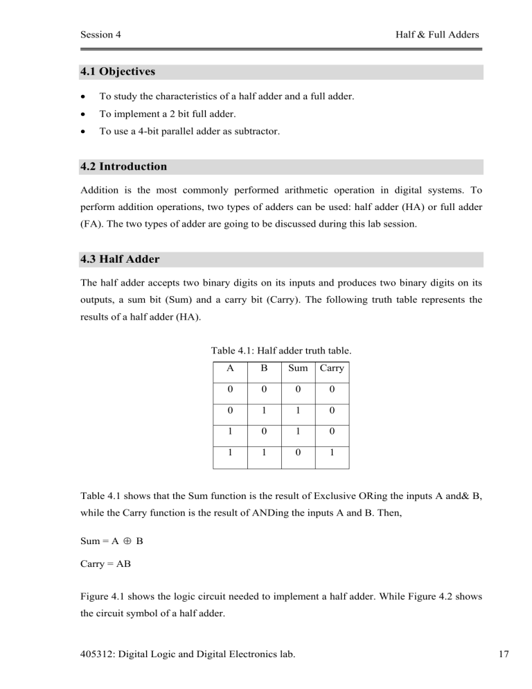
The half adder accepts two binary digits on its inputs and produces two binary digits on its outputs, a sum bit (Sum) and a carry bit (Carry). The following truth table represents the results of a half adder (HA).
Table 4.1: Half adder truth table.
0 0 0 0
0 1 1 0
1 0 1 0
1 1 0 1
Table 4.1 shows that the Sum function is the result of Exclusive ORing the inputs A and& B, while the Carry function is the result of ANDing the inputs A and B. Then,
Sum = A
⊕
B
Carry = AB
Figure 4.1 shows the logic circuit needed to implement a half adder. While Figure 4.2 shows the circuit symbol of a half adder.
405312: Digital Logic and Digital Electronics lab. 17
Session 4 Half & Full Adders
Figure 4.1: Half adder circuit diagram .
Figure 4.1: Half adder circuit symbol.
4.4 Full Adder
The full adder accepts two input bits A and B and an input carry C and generates a sum output (Sum) and output carry (Cout). The following truth table represents the results of a full adder (FA).
Table 4.2: Full adder truth table.
0 0 0 0 0
0 0 1 1 0
0 1 0 1 0
0 1 1 0 1
1 0 0 1 0
1 0 1 0 1
1 1 0 0 1
1 1 1 1 1
405312: Digital Logic and Digital Electronics lab. 18
Session 4 Half & Full Adders
Using K-map to simplify the Sum function of the FA shown by Table 4.2, the following is obtained:
Sum = A'B'C+A'BC'+AB'C'+ABC
= A'(B'C+BC') + A(BC+B'C')
= A'(B C) + A(B C)
= A'(B C) + A(B C)'
= A B C
Studying Table 4.2 carefully, you will find that Carry function (Cout) can be represented as follows:
Cout = AB + (A B).C
Figure 4.3 shows the full adder circuit diagram. While Figure 4.4 shows the full adder circuit symbol.
Figure 4.3: Full adder circuit diagram.
Figure 4.4: Full adder circuit symbol.
Note: 74LS83 IC chip is a 4 bit binary parallel full adder that can perform the addition operation on two 4 bit numbers.
405312: Digital Logic and Digital Electronics lab. 19
Session 4
4.5 Subtraction
Half & Full Adders
Since subtraction is a special case of addition, it is possible to perform subtraction of binary numbers in 2 nd
complement
form using the circuit of full adders. Only the second operand must be converted into its 2 nd
complement before performing the addition operation. Then, in order to subtract, use the same FA circuit described before with another circuit to find the 2 nd complement.
Remember that;
1 1=0
0 1 1
Then the XOR function obtains the 1 st complement of a binary number, and adding 1 to the
1 st complement gives the
2 nd complement. Thus, the circuit needed to find the
2 nd complement is only an XOR gait and adding 1 to the carry bit of the FA. Figure 4.5 shows a
FA used as subtractor.
Figure 4.5: 1-bit subtractor circuit.
Pre-Lab 4
1Find the result of the following operations, then find the equivalent decimal value of the operation to check your answer. (represent the negative numbers using 2 nd complement) a) 1011+0001= b) 1001-0100 = c) 0100-0110 =
2Construct a 4-bit full adder using the full adder symbol shown in Figure 4.4.
Lab Work 4
Use the 4-bit binary adder IC 74ls83 and the XOR gate 74ls86 to build a circuit that adds/subtracts 2 4-bit binary numbers. Use this circuit to check your answers in question 1.
405312: Digital Logic and Digital Electronics lab. 20
Session 4 Half & Full Adders
Homework 4
Design a logic circuit using the full adder shown in Figure 4.6 to build a 4-bit full adder/subtractor. where,
The numbers are A
3
A
2
A
1
A
0
and B
3
B
2
B
1
B
0
.
You are required to build the circuit using MultiSIM.
Figure 4.6: 1-bit full adder circuit symbol.
405312: Digital Logic and Digital Electronics lab. 21


