Experiment #2: Spatial Filtering. Part B.
advertisement

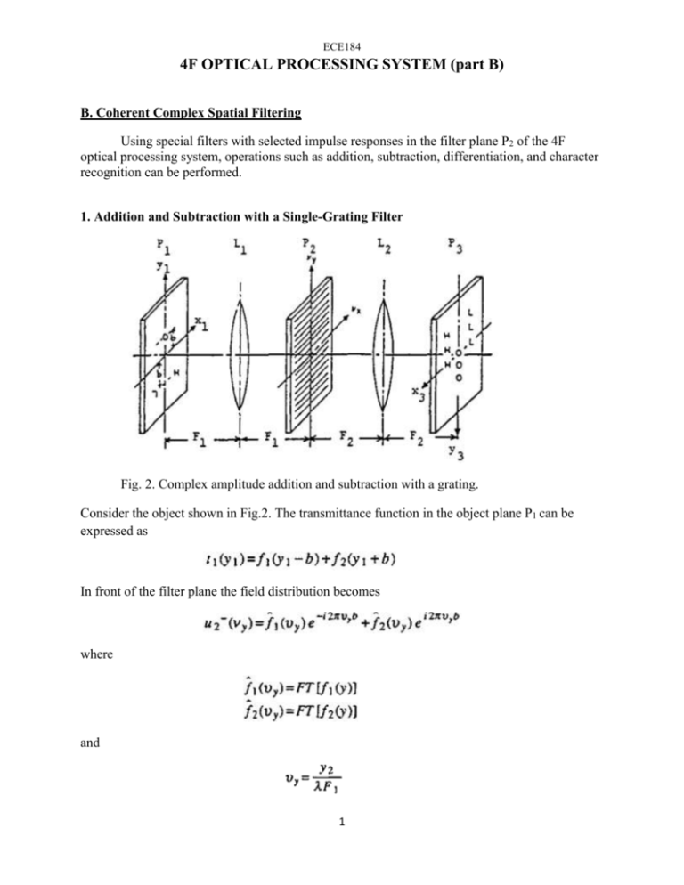
ECE184 4F OPTICAL PROCESSING SYSTEM (part B) B. Coherent Complex Spatial Filtering Using special filters with selected impulse responses in the filter plane P2 of the 4F optical processing system, operations such as addition, subtraction, differentiation, and character recognition can be performed. 1. Addition and Subtraction with a Single-Grating Filter Fig. 2. Complex amplitude addition and subtraction with a grating. Consider the object shown in Fig.2. The transmittance function in the object plane P1 can be expressed as In front of the filter plane the field distribution becomes where and 1 The filter is a grating with transmittance which can be made by interfering two plane wave incident on a piece of film, with a small angle between the two propagating directions. These two wave planes can be generated with two off-axis point sources as shown on Fig.3. Fig. 3. Optical system for producing a cos2(πυyb) grating The amplitude distribution immediately behind the grating is The lens L2 forms the Fourier transform of u2+(υy) at its back focal plane P3, so Hence, at the center portion of the image plane, we have the addition of the two complex functions f1 and f2. If the transmittance of the grating is which corresponds to having the maximum transmittance of the grating shifted by a quarter of a fringe spacing from the optical axis, and 2 and thus Therefore, at the center portion of the image plane, we have the subtraction of the two complex functions f1 and f2. 2. Differentiation with a Double-Grating Filter A filter which is composed of two gratings of slightly different frequencies, and shifted by one half of a fringe spacing, will have the transmittance function where ε is small positive number. By inserting this filter in the Fourier plane P2 , and using an object with amplitude distribution f(x,y) at the input plane P1, the light field at the output is The last terms are proportional to the differentiation operation ∂f/∂y since 3. Vander Lugt Filter First consider how this particular filter is synthesized, see Fig.4(a). Lens L1 collimates light from the point source S. The lower portion of this collimated beam strikes the mask which has the desired impulse response h. Lens L3 Fourier transforms the amplitude distribution h, yielding an amplitude distribution 3 incident on the film. A smaller lens L2 focuses the upper portion of the collimated beam to a bright spot at the focal plane of lens L3. When the spherical wave generated by this reference point passes through L3, it is collimated to produce a tilted plane wave at the film with the field distribution: Fig.4. (a) a modified Rayleigh interferometer system to produce the Vander Lugt filter, (b) location of the four terms of the processor output where Wh and Wg are the maximum width of h and g, respectively. where the spatial frequency α is given by and ϴ is the tilt angle. The total intensity distribution on the film is The film is then exposed and developed to produce a transparency with an amplitude transmittance proportional to the intensity distribution incident on the film during exposure. Thus 4 Once the film of transmittance t(x2, y2) has been synthesized, it may be inserted in the transform plane P2 of the 4F optical processing system. If the input function is g(x1, y1), then the amplitude distribution incident on the transform plane is The field amplitude after the filter is The final lens L3 Fourier transforms u2. Taking note of the reflected coordinated system in the plane P3, the field in that plane is The third term in u3 has the form This portion of the output is seen to yield the convolution of h and g at coordinates (0, -αλF) in the x3y3 -plane, as shown in Fig.4(b). The forth term has the form which is the cross-correlation of g and h centered at coordinates (0, αλF) in the x3y3 –plane. From the Fig.4.(b) it is clear that complete separation will be achieved if 5 EXPERIMENTS B. Coherent Complex Spatial Filtering 1. Coherent Addition and Subtraction Filter. - A spatial filter consisting of a cos2 - grating has an impulse response of three delta functions. This filter can be used in the system of Fig. 2 to perform addition and subtraction. - Place filter marked "addition/subtraction" in filter plane. Using the twin-triangle objects (one with triangles spaced 2b apart and another with triangles spaced 4b apart) in the object plane, perform addition and subtraction of the images. 2. Differentiation Filter. By superimposing two gratings of slightly different frequencies and shifted by a half of a period, a filter capable to perform the differentiation can be generated. When this filter is placed in the filter plane, spatial differentiation is performed on the image in the first diffraction order. - Place filter marked "differentiation" in the filter plane and perform differentiation in xdirection on letter "T". - Perform differentiation on letter T in y-direction. 3. Vander Lugt Filter Note: The character "AE" was used as the desired impulse response in Fig. 4(a) to generate a Vander Lugt filter. - Place slide with symbol AE in the object plane. - Look on VDL filter and find the spot where the object recorded (“sparkling dot” on the slide) - Place the VDL filter in the filter plane to perform character recognition by correlation. 6 - Adjust filter position to illuminate the “sparkling dot”. As result you should see three spots on the screen before the image plane. - Place CCD camera into upper spot (in our case it is the cross-correlation area) and observe the response. Fine tune filter position to get the brightest intense small spot. (Reduce light intensity to prevent saturation of CCD if needed.) - Replace symbol AE by letter A (E, and S) and observe the response. - Analyze your observed results. Does symbol AE give the brightest spot? - Verify the content of VDL filter by placing the filter in the object plane and observing its Fourier transform. 7


