Introduction: The Rankine cycle closely describes the process by
advertisement
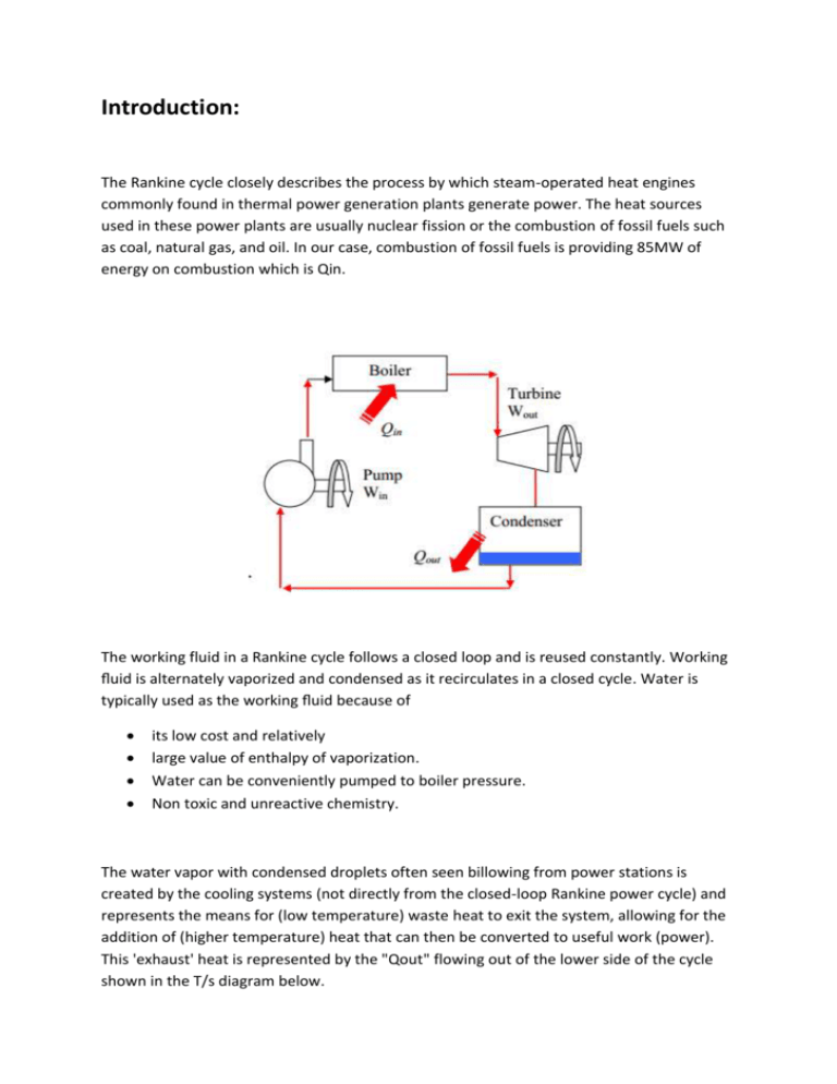
Introduction: The Rankine cycle closely describes the process by which steam-operated heat engines commonly found in thermal power generation plants generate power. The heat sources used in these power plants are usually nuclear fission or the combustion of fossil fuels such as coal, natural gas, and oil. In our case, combustion of fossil fuels is providing 85MW of energy on combustion which is Qin. The working fluid in a Rankine cycle follows a closed loop and is reused constantly. Working fluid is alternately vaporized and condensed as it recirculates in a closed cycle. Water is typically used as the working fluid because of its low cost and relatively large value of enthalpy of vaporization. Water can be conveniently pumped to boiler pressure. Non toxic and unreactive chemistry. The water vapor with condensed droplets often seen billowing from power stations is created by the cooling systems (not directly from the closed-loop Rankine power cycle) and represents the means for (low temperature) waste heat to exit the system, allowing for the addition of (higher temperature) heat that can then be converted to useful work (power). This 'exhaust' heat is represented by the "Qout" flowing out of the lower side of the cycle shown in the T/s diagram below. Cooling towers operate as large heat exchangers by absorbing the latent heat of vaporization of the working fluid and simultaneously evaporating cooling water to the atmosphere. By condensing the working steam vapour to a liquid the pressure at the turbine outlet is lowered and the energy required by the feed pump consumes only 1% to 3% of the turbine output power and these factors contribute to a higher efficiency for the cycle. Analysis of processes: Process 1-2: Water from the condenser at low pressure is pumped into the boiler at high pressure. This process is reversible adiabatic. Process 2-3: Water is converted into steam at constant pressure by the addition of heat in the boiler. Process 3-4: Reversible adiabatic expansion of steam in the steam turbine. Process 4-1: Constant pressure heat rejection in the condenser to convert condensate into water. Thermal Efficiency Of Rankine Cycle: h=enthalpy q=heat w=work Consider one kg of working fluid, and applying first law to flow system to various processes with the assumption of neglecting changes in potential and kinetic energy, we can write,dqdw=dh For process 2-3, δ = w 0 (heat addition process), we can write, (dq)boiler=(dh)boiler=(h3-h2) For process 3-4; δ = q 0(adiabatic process), (dw)turbine=-(dh)turbine=(h3-h4) Similarly, (dq)condenser=(h1-h4) (dw)pump=(h1-h2) (dw)net=(dw)turbine+(dw)pump=(h3-h4)+(h1-h2)=(h3-h4)-(h2-h1) Thermal efficiency = Nth=Net Work/Heat Supplied=(dw)net/(dq)boiler =[(dw)turbine-(dw)pump]/Qin Calculations: Let us assume that Steam enters the turbine at P1 MPa(say) and 500oC and is cooled in the condenser to a pressure of P2 kPa(say). To compute the quality at the turbine exit, we recognize that this exit state is defined by the condenser pressure of P2 KPa and an isentropic process such that sout = sin = s(P1 MPa, 900oC).[see seam tables]. Quality= [sout-sf(P2)]/sfg(P2) In order to compute the efficiency, we need the enthalpy values at all the state points. Following a conventional Rankine cycle calculation, we find the properties at state one as those of a saturated liquid at the condenser pressure: h1 = hf(P2 kPa) and v1 m3/kg. The isentropic pump work, |wp1| = v1(P2 – P1) where P2 is the same as the inlet pressure to the turbine. We then find h2 = h1 + |wp1| h3=h[P2, 900C] As noted above, state 4 is in the mixed region with P4 = P2 kPa and s4 = quality. We thus find the enthalpy from the quality as h4 = hf(P4 =P2 KPa) + x4 hfg(P4 = P2 kPa). We can directly calculate thermal efficiency by putting the given values in formula derived in previous section(multiplying by respective efficiency). (dw)turbine=0.92*(h3-h4) (dw)pump=0.85*(h2-h1) Qin=(h3-h2) Power production=Net work done Entropy production can be seen as difference in entropy values seen from steam tables. Mass flow can be calculated as (85MW)/ [(dw)turbine-(dw)pump] So, the Rankine cycle is designed. Modifications in Rankine Cycle(to achieve higher efficiency): Superheating and reheating The irreversibility of any process is reduced if it is performed as close as possible to the temperatures of the high temperature and low temperature reservoirs. This is achieved by operating the condenser at sub-atmospheric pressure. The temperature in the boiler is limited by the saturation pressure. Further increase in temperature is possible by superheating the saturated vapour. This has the additional advantage that the vapor quality after the turbine is increased and, therefore the erosion of the turbine blades is reduced. It is quite common to reheat the vapor after expansion in the high pressure turbine and expand the reheated vapor in a second, low pressure turbine. Feed water preheating The cold liquid leaving the feed pump is mixed with the saturated liquid in the boiler and/or re-heated to the boiling temperature. The resulting irreversibility reduces the efficiency of the boiler. According to the Carnot process, the highest efficiency is reached if heat transfer occurs isothermally. To preheat the feed liquid to its saturation temperature, bleed vapor from various positions of the turbine is passed through external heat exchangers (regenerators). Ideally, the temperature of the bleed steam should be as close as possible to the temperature of the feed liquid. <Values in figure are indicative only> Combined cycles The high combustion temperature of the fuel is better utilized if a gas turbine or Brayton engine is used as "topping cycle" in conjunction with a Rankine cycle. In this case, the hot gas leaving the turbine is used to provide the energy input to the boiler. In cogeneration systems, the energy rejected by the Rankine cycle is used for space heating, process steam or other low temperature applications.
