experiment note
advertisement
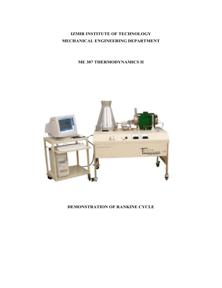
IZMIR INSTITUTE OF TECHNOLOGY MECHANICAL ENGINEERING DEPARTMENT ME 307 THERMODYNAMICS II DEMONSTRATION OF RANKINE CYCLE Purpose of the experiment The aim of this experiment is to understand Rankine Cycle System with the details of each component, conduct the experiment and gather data and finally analyze the system with acquired data. Components of the system Figure 1 illustrates the whole components of the system. In this section, the components will be explained briefly. Figure 1. Rankine Cycle Experimental Set-up 1. Boiler: Dual-pass flame tube system The Rankine Cycler boiler is a dual-pass, flame through tube-type unit as shown in the left in Fig. 2. A forced air gas burner fires it. The burner fan speed is electronically adjustable to operate with a minimum of excess air. The system’s purpose-built burner fan results in extremely clean combustion while burning LP gas. A vortex disc, located downstream of the blower unit as illustrated in the right of Fig. 2, mixes fuel and air and sets up a vortex gas flow that results in efficient heat transfer from the flame tube to the boiler’s water. Figure 2. Steam Generation Boiler and Burner 2. Steam Turbine: The steam turbine, shown at the left side of Fig. 3, consists of the following major components: 1. A precision machined, stainless steel front and rear housing. 2. Front and rear bronze bearings. 3. Front and rear bearing oilers. 4. A stainless steel shaft. 5. A nozzle ring and a single stage shrouded impulse turbine wheel. Figure 3. Steam Turbine and Generator The generator, shown at the right side of Fig. 3, is a 4-pole, permanent magnet, brushless unit. The rotor is supported by pre-loaded precision ball bearings. The generator includes a full wave, integral rectifier bridge that delivers direct current to the generator’s DC terminals. The generator’s terminal board also carries a set of AC output terminals for experimental procedures that may entail the use of a transformer, or deal with frequency related topics, RPM measurement, and other AC related experiments. 3. Condensing Tower: The condenser tower’s outer mantle is formed from a single piece of aluminum. The tower’s large surface area affects heat transfer to ambient air and provides a realistic appearance. Turbine exhaust steam is piped into the bottom of the tower. The steam is kept in close contact with the outside mantle by means of 4 baffles. A drain hose and clamp are located at the left rear of the system. Following an experiment, the condensate can be drained into a beaker and measured. Figure 4. Condensing Tower 4. Sight Glass A sight glass is provided to indicate boiler water level. Two level indicators, set by thumbscrew bezels, can be adjusted at the beginning and end of each experiment to determine steam rate (water volume divided by start and stop times). Experimental Procedure Follow these steps to operate Rankine Cycle System: Fill the boiler with 6 liters of water. Be sure Steam Admission valve is closed. Open the fuel source. Open the gas valve. Turn to master switch on. Turn the burner switch on. Verify lit on burner in 45 seconds (After burner lits, pressure in the boiler will start to raise. By this time connect the computer to the system and start to record data.) Wait until pressure in the boiler reaches 110 psi. After reaching 110 psi, open the steam admission valve to drop pressure to 40 psi then close the valve. Repeat the process above. When pressure reaches 110 psi again, open the valve slowly without decreasing pressure too much. Open the load switch. Now amp meter should show like 0.2 amps while volt meter shows 6 volts. Adjust steam admission valve and load rheostat to achieve steady state condition for: 110 psi pressure, 0.2 amp and 6 volts. Note steady state starting time and continue experiment for 10 minutes. Finish the experiment by: Close gas valve and burner Open steam admission valve till turbine stops Close master switch Note condensation amount from condensation water. Empty boiler tank and note water amount. Calculations and Results Collected data will be given to you in Excel format. First of all you will plot the following graphs. Fuel flow vs time Boiler temperature vs time Boiler pressure vs time Turbine inlet/outlet pressure vs time Turbine inlet/outlet temperature vs time Generator dc amps output vs time Generator dc voltage output vs time Turbine rpm vs time In the graphs you will choose a steady state period for 5-10 minutes. For this period note the following data to be able to use in calculations: Atmospheric pressure Initial boiler fill amount Fuel flow Boiler pressure Turbine inlet pressure Turbine inlet temperature Turbine outlet temperature Turbine outlet pressure Steady State Condensation amount For analysis assume a steady state, steady flow condition. Changes in kinetic and potential energy are negligible. Calculate the listed data above: Heat flow out of boiler Work rate of the turbine Efficiency of electric generator Heat flow rate out of the system at the condenser Condenser efficiency Total system efficiency
