ME495 Lab - Rankine Cycle
advertisement
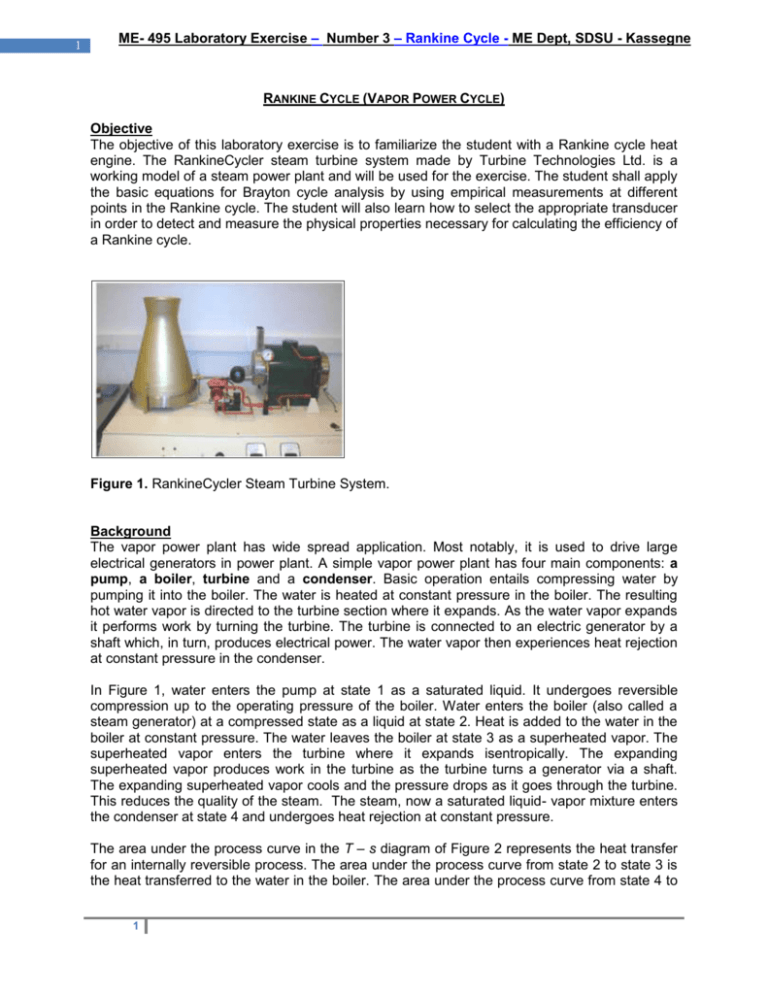
1 ME- 495 Laboratory Exercise – Number 3 – Rankine Cycle - ME Dept, SDSU - Kassegne RANKINE CYCLE (VAPOR POWER CYCLE) Objective The objective of this laboratory exercise is to familiarize the student with a Rankine cycle heat engine. The RankineCycler steam turbine system made by Turbine Technologies Ltd. is a working model of a steam power plant and will be used for the exercise. The student shall apply the basic equations for Brayton cycle analysis by using empirical measurements at different points in the Rankine cycle. The student will also learn how to select the appropriate transducer in order to detect and measure the physical properties necessary for calculating the efficiency of a Rankine cycle. Figure 1. RankineCycler Steam Turbine System. Background The vapor power plant has wide spread application. Most notably, it is used to drive large electrical generators in power plant. A simple vapor power plant has four main components: a pump, a boiler, turbine and a condenser. Basic operation entails compressing water by pumping it into the boiler. The water is heated at constant pressure in the boiler. The resulting hot water vapor is directed to the turbine section where it expands. As the water vapor expands it performs work by turning the turbine. The turbine is connected to an electric generator by a shaft which, in turn, produces electrical power. The water vapor then experiences heat rejection at constant pressure in the condenser. In Figure 1, water enters the pump at state 1 as a saturated liquid. It undergoes reversible compression up to the operating pressure of the boiler. Water enters the boiler (also called a steam generator) at a compressed state as a liquid at state 2. Heat is added to the water in the boiler at constant pressure. The water leaves the boiler at state 3 as a superheated vapor. The superheated vapor enters the turbine where it expands isentropically. The expanding superheated vapor produces work in the turbine as the turbine turns a generator via a shaft. The expanding superheated vapor cools and the pressure drops as it goes through the turbine. This reduces the quality of the steam. The steam, now a saturated liquid- vapor mixture enters the condenser at state 4 and undergoes heat rejection at constant pressure. The area under the process curve in the T – s diagram of Figure 2 represents the heat transfer for an internally reversible process. The area under the process curve from state 2 to state 3 is the heat transferred to the water in the boiler. The area under the process curve from state 4 to 1 2 ME- 495 Laboratory Exercise – Number 3 – Rankine Cycle - ME Dept, SDSU - Kassegne state 1 is the heat rejected in the condenser. The difference between the two (the area within the process cycle) represents the net work produced by the cycle. To perform the thermodynamic analysis on the cycle each component is modeled as a control volume. All processes are executed in steady-flow sections and can be analyzed as a steadyflow process, expressed on a basis of unit mass as q – w = hexit – hinlet. The boiler and condenser do involve work and the turbine is considered to be isentropic. Additionally, there is one flow in to each device and one flow out of each device. Under consideration of all of these conditions the specific first law analysis for each device is: Pump – (q = 0): win,PUMP = h2 – h1 Boiler (w = 0): qin = h3 – h2 Turbine (q = 0): wout,TURB = h3 – h4 Condenser (w = 0): qout = h4 – h1 The thermal efficiency of the Rankine cycle is determined from: th = wnet = 1 – qout qin qin Where wnet = qin – qout = wout,TURB – win,PUMP The RankineCycler used in this lab exercise does not make use of pump to compress water. The boiler is filled to ¾ capacity with water prior to operating the lab. The water is heated at constant volume by a flame fueled with liquid propane (LP). The heat addition process under constant volume conditions causes a pressure increase. The high pressure water vapor is directed to the turbine where it expands and drives the electrical generator via a pair of spring shafts connecting the turbine and generator. The water vapor steam mixture experiences constant pressure heat rejection in the cooling tower where the water condenses into a catch tube. 2 3 ME- 495 Laboratory Exercise – Number 3 – Rankine Cycle - ME Dept, SDSU - Kassegne Figure 1: Summary of Rankine Cycle. Figure 2: T – s diagram for a simple Rankine cycle. 3 4 ME- 495 Laboratory Exercise – Number 3 – Rankine Cycle - ME Dept, SDSU - Kassegne Operating Procedure 1. Fill the boiler with DI water. You can get DI water from the Cleanroom area (Room No. EL103C). a. Open Steam Admission Valve. b. Insert filler tube in back of boiler. c. Fill 3500ml of water using the graduated cylinder. d. Remove the filler tube e. Close the Steam Admission Valve. 2. Lock the casters. 3. Remove the two brass thumbscrews from the turbine. 4. Check that the oil level is within 1/8 inch from the top of the fitting. a. If the oil level is low consult the lab instructor for the tooling and material to adjust the oil level. 5. Turn the load switch to “OFF”. 6. Turn the burner switch to “OFF”. 7. Turn the load rheostat knob fully counter clockwise. 8. Drain any condensate from the cooling tower catch tube. 9. Turn on the power strip to the computer and RankineCycler test bench. 10. Open the valve on Liquid Propane (LP) tank. 11. Rotate the Gas Valve knob on the left front side of the test bench to “ON”. 12. Turn on master power switch on the test bench “ON” (green indicator should light). 13. Turn the burner switch “ON” (green indicator should light). a. The turbine in the ignition unit will start. b. Stay clear of the ignition unit. After a brief time (20 - 30 seconds) the piezo element will ignite the LP. There may be a loud pop upon ignition and a flame may shoot from the igniter turbine. 14. Allow the pressure in the boiler to build to. The pressure gage should begin to show an indication after about three minutes. Do not allow the pressure to exceed 110 psig. 15. Open the “Virtual Bench” on the computer desktop. 16. Select Edit>>Settings. 17. Open the File Configuration dialog box. 18. Enter a Filename. 19. Enter a Username, Comments, Field Length, Precision, and Number of Lines to write to the file. 4 5 ME- 495 Laboratory Exercise – Number 3 – Rankine Cycle - ME Dept, SDSU - Kassegne 20. Select Enable Logging. 21. To begin logging to disc automatically when acquisition starts, select Begin Logging on Start. 22. Select OK. All of the configured channels will now log to your disc. 23. Open the Timing Configuration dialog box. 24. Select a time interval and a log to disc every n time interval 25. Select OK. 26. You have now enabled logging to disc. If you selected begin logging on start in the File Configuration dialog box. VirtualBench-Logger immediately begins logging data to the disc when you begin acquiring data. Else, you can control logging to disc manually by using the Logging “ON” and “OFF” options to the left of the data acquisition controls. 27. After the boiler pressure reaches 110 psig, observe the voltmeter and slowly open the Steam Admission Valve. 28. Regulate the turbine speed until the voltmeter indicates between 7 and 10 volts. a. This will preheat the turbine components and tubing. b. Close the Steam Admission Valve after 20 seconds and allow the boiler pressure to rebuild. 29. After the boiler pressure reaches 110 psig, open the Steam Admission Valve and adjust the turbine until the voltmeter indicates 9 volts. 30. Turn the load switch “ON”. 31. Slowly adjust the Load knob along with the Steam Admission Valve until 9 volts and 0.4 amps are indicated on the voltmeter and ammeter, respectively. 32. Adjust the Steam Admission Valve to maintain steady state indications on the voltmeter and ammeter. 33. Close the steam admission Valve. 34. Turn the load knob full counter clockwise and turn the Load switch to “OFF”. 35. Turn the Burner switch “OFF” 36. Turn the gas valve on the test bench “OFF”. 37. Close the valve on the LP tank. 38. Drain the condensate from the cooling tower into a graduated cylinder and record the volume. 39. Allow the boiler pressure to reduce to 10 psig via cooling. 40. Turn on the load to full and open the Steam Admission Valve until boiler pressure is equal to atmospheric pressure. Caution: do not over spin the turbine! 5 6 ME- 495 Laboratory Exercise – Number 3 – Rankine Cycle - ME Dept, SDSU - Kassegne 43. Measure the amount of water used during your test run. a. Insert filler tube in back of boiler. b. Takeout the remaining water in the graduated cylinder and measure the volume. c. Record the amount of water replaced in the boiler. d. Remove the filler tube e. Close the Steam Admission Valve. Data Reduction 1. The measured or weighted re-fill mass of water represents the boiler’s total steam production during your run. This can be correlated as the steam rate by dividing the weight of the water replaced by the time duration of your run. 2. Provide a first law analysis of each stage of the actual process. 3. Calculate the efficiency for the turbine. 6

