3 - Creating a Contour
advertisement
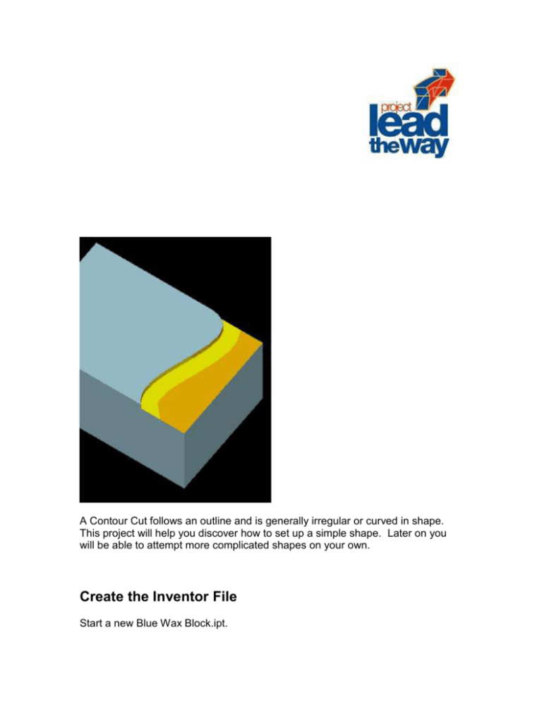
Creating a Contour A Contour Cut follows an outline and is generally irregular or curved in shape. This project will help you discover how to set up a simple shape. Later on you will be able to attempt more complicated shapes on your own. Create the Inventor File Start a new Blue Wax Block.ipt. Figure 1 Create a sketch environment on the block by highlighting the front of the block and depressing the Sketch Button on the Command Tool Bar. To create the contour the spline tool from the 2D Sketch Panel will be used. Figure 2 Figure 3 Place 4 to five points on the face of the block beginning on the top edge and ending on the bottom edge. Right click to select Continue, then right click and select done. Finish the sketch. Extrude the sketch a distance of .1 and use Cut for an option. Figure 4 Save your file. Creating the Geometry in EdgeCAM In this exercise we will be using the Inch settings in Edge Cam. Set the Inch Default settings by going to the options menu and choose the �Select Defaults� option. In the dialog box browse to C:\Program Files\EdgeCAM\Cam\Support and select the mill_in.dft file. Before leaving the dialog box you should select the �Selected File� for the option on Load on Entry option. See figure 5 Figure 5 This will set your defaults so that the next file you open will be used with a template based on inch measurements. Open the blue wax block you created in Inventor. Don�t worry if you cannot see your block when done Place the block in an isometric view by selecting isometric from the options found by clicking on the bottom left hand corner of the drawing screen. Figure 6 Now you can make the block visible by zooming to extents with either the icon or by using Ctrl E Key strokes. Figure 7 The block with the CPL (Construction Plane) symbol in the 0,0,0 position should now be visible. Figure 8 There are many ways to produce the toolpath with EdgeCAM and only one scenario will be presented here. Some of the elements of geometry must be identified before the toolpaths can be configured. The first piece of geometry necessary to create the toolpath is the contour. We can identify this by selecting the Profile Identifier from the Superseded section of the Solids pulldown menu. Figure 9 Give the operation a name, and select individual Edges select OK and then click on the contour line. Right click to exit the picking mode. Figure 10 You will then be asked for a point to digitize the depth. Select the point at the bottom of the contour profile as in figure 11. Figure 11 The command should complete and the Curve should show up on the features menu. Figure 12 The last step is to create the stock that will be machined. Select the Autostock icon from the Design Toolbar or from the Geometry pull down menu.. Figure 13 Place a check in the Autostock check box at the top of the dialog box and select OK. Once you have finished this save your file. Creating the Toolpath Enter the Manufacture section of the program by selecting the Manufacture Icon from the Standard Toolbar. Figure 14 Select the Prolight milling machine if that is the correct one for your lab and give the operation a unique name. This one was called Contour. Figure 15 There are many different ways of creating these toolpaths. For this exercise the tool will be chosen before selecting the cycle or operation. Select Toolstore from the Tooling pull down menu to bring up the list of tools to choose from. Figure 16 The �� End Mill has been selected here to perform the operation. Depress the select button and the dialog box for the tool appears. Accept the defaults by selecting OK and it should appear in the Instructions tab of the browser. We can now select 2D Profile from the Mill Cycles pull down menu. The Profile dialog box appears. Figure 17 Since we are creating an NC file we will let Pathtrace control the compensation. A Climb Mill Type is used. The feed rate has been changed to 20 Inches per minute, a speed that the Prolight mill works well with. The plunge rate has been reduced to 10 inches per minute. Figure 18 On the Depth tab the depth has been set to a -0.1 and a Retract setting of .1 has been used. See figure 19 for an explanation of the definitions. Figure 19 Figure 20 depicts the Lead tab. This tab controls the movement of the cutter on the way in and out. In this example the curve of the contour must be extended so that the cut is smooth. The profile extension is .3, or just over the size of the cutter bit, at either end of the profile. Figure 20 Figure 21 details the Contouring tab. The example used here is a very simple so many of the settings are not used. You can access the help menu for detailed explanations of what those settings control. Here the cut increment is .05 so two passes will be necessary to cut to the entire depth. The �Stay at Depth� check box is unchecked to prevent the milling machine returning through the part to make the second pass. If you wanted to save time and your milling machine can handle the cut you can leave the cut increment blank and the mill will take the cut in a single pass. Figure 21 When you are done you can select OK. The prompt will ask you to select the �Line/Arc/Continuous/Group as Profile�. Sometimes the easiest way to select the geometry is to select the features tab and highlight the choice there. Figure 22 Verify the Toolpath To verify the machining select the Verify Machining icon on the Main Tool Bar. Figure 23 This will bring up the Verify window. Press the play button on the Simulator tool bar. Figure 23 The simulation should look similar to figure 24. Figure 24 Exit the simulation mode and save the part. The next step is to remove the rest of the material on the right hand side of the block. There are many ways to do this. The choice here is to make a copy of the tool path and to move it over a little on each pass. From the Edit pull down menu select Translate. Figure 25 In the Translate Machining dialog box enter .125 for an X Increment.� This will move the cut over 50% of the cutter on each pass. Since this is a simple tool path use the Browse button next to the From Window and select the Profile Milling we just did.� Repeat the Process for the To window.� Set the repeats to enough to finish the cut.� In this case 5 passes will be used.� This can be edited later if you have too many or too few. Figure 26 You should now see multiple passes of your toolpath. Figure 27 Verify your part again to be sure you have the cut you want. Generating the NC Code Use the Generate Code button to generate the NC code file. Figure 28 In the dialog box enter the name to be associated with this file. Select OK Figure 29 The prompt will ask for the number and programmers name. Once the name is entered the code will be generated. Figure 30

