Prelab9 Solutions 2)
advertisement
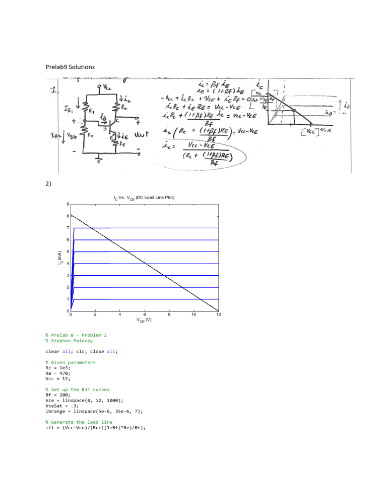
Prelab9 Solutions
2)
IC Vs. VCE (DC Load Line Plot)
9
8
7
IC (mA)
6
5
4
3
2
1
0
0
2
4
6
VCE (V)
% Prelab 8 - Problem 2
% Stephen Maloney
clear all; clc; close all;
% Given parameters
Rc = 1e3;
Re = 470;
Vcc = 12;
% Set up the BJT curves
Bf = 200;
Vce = linspace(0, 12, 1000);
VceSat = .3;
ibrange = linspace(5e-6, 35e-6, 7);
% Generate the load line
ill = (Vcc-Vce)/(Rc+((1+Bf)*Re)/Bf);
8
10
12
% Plot a range of ib values
for ib = ibrange
ic = bjt(Vce, ib, Bf, VceSat);
plot(Vce, ic*1e3, 'Linewidth', 2);
hold on;
end
% Add load line
plot(Vce, ill*1e3, 'k--', 'LineWidth', 2);
% Label the graph
xlabel('V_C_E (V)'); ylabel('I_C (mA)');
title('I_C Vs. V_C_E (DC Load Line Plot)');
4) As can be seen from the Spice DC-Operating point simulations below, βf changing over quite a large
range does not produce an extreme swing in operating point due to the feedback resistor, RE = R4.
11)
With RE = R4 in the circuit:
VOut ,Open
VOut
I
V
= ROut ≈ 1075.84Ω
≈ −1.033 Out ≈ −.967 In = RIn ≈ 935Ω
VIn
I In
I In
I Out ,Short
Note - to measure ROut you have to rerun the simulation first removing the load and measuring Vout to
find the open circuit voltage output, then short the load and measure the short circuit current.
Without RE = R4 in the circuit:
V
VOut
I
V
≈ −50.13 Out ≈ −28.28 In = RIn ≈ 564.18Ω Out ,Open = ROut ≈ 1065.69Ω
I Out ,Short
VIn
I In
I In
