University of Babylon /College Of Engineering Electrochemical Engineering Dept. Second Stage /Thermodynamics
advertisement
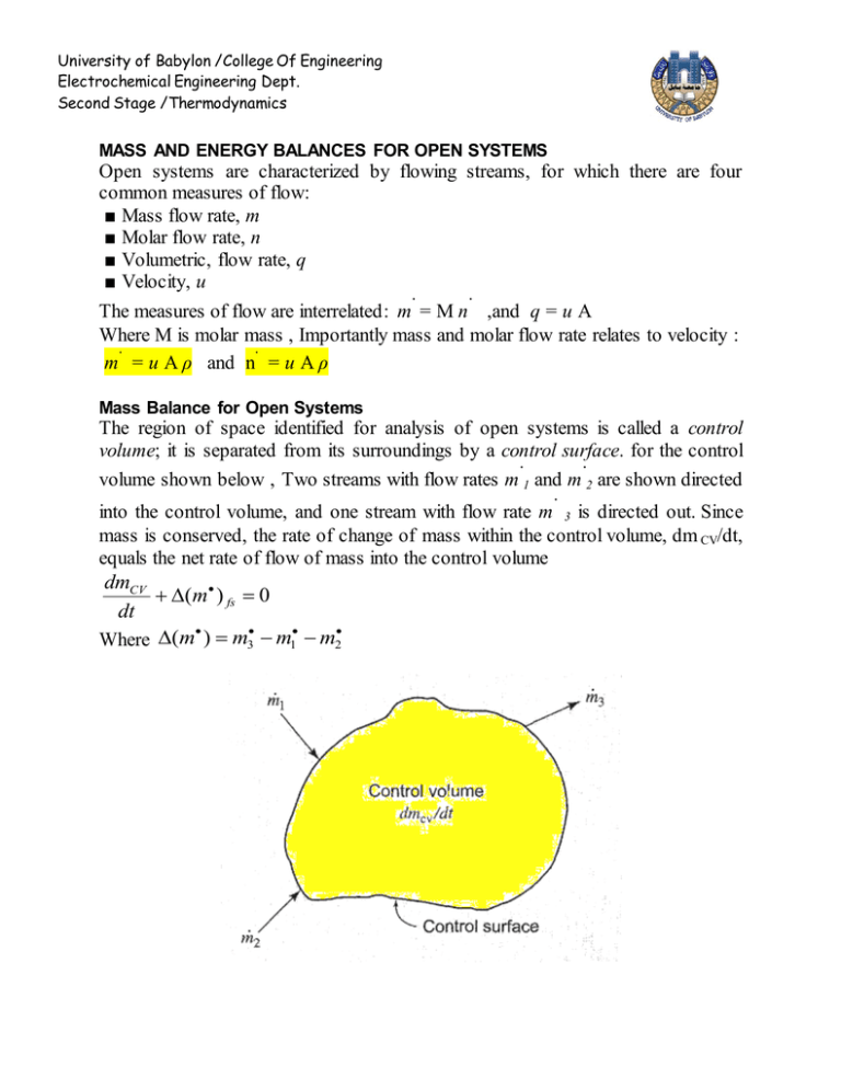
University of Babylon /College Of Engineering Electrochemical Engineering Dept. Second Stage /Thermodynamics MASS AND ENERGY BALANCES FOR OPEN SYSTEMS Open systems are characterized by flowing streams, for which there are four common measures of flow: ■ Mass flow rate, m ■ Molar flow rate, n ■ Volumetric, flow rate, q ■ Velocity, u ∙ ∙ The measures of flow are interrelated: m = M n ,and q = u A Where M is molar mass , Importantly mass and molar flow rate relates to velocity : ∙ ∙ m = u A ρ and n = u A ρ Mass Balance for Open Systems The region of space identified for analysis of open systems is called a control volume; it is separated from its surroundings by a control surface. for the control ∙ ∙ volume shown below , Two streams with flow rates m 1 and m 2 are shown directed ∙ into the control volume, and one stream with flow rate m 3 is directed out. Since mass is conserved, the rate of change of mass within the control volume, dm CV/dt, equals the net rate of flow of mass into the control volume dmCV (m ) fs 0 dt Where (m ) m3 m1 m2 University of Babylon /College Of Engineering Electrochemical Engineering Dept. Second Stage /Thermodynamics dmCV ( uA) fs 0 dt In this form the mass-balance equation is often called the continuity equation. At steady state there is no accumulation , thus ; ( uA) fs 0 For a system with single entrance and single exit, the mass flow rate is the same for both streams ; then 2u2 A2 1u1 A1 0 or m const 2u2 A2 1u1 A1 Since specific volume is reciprocal of density u A u A uA m 2 2 1 1 V2 V1 V The General Energy Balance Since energy, like mass, is conserved, the rate of change of energy within the control volume equals the net rate of energy transfer into the control volume. Streams flowing into and out of the control volume have associated with them energy in its internal, potential, and kinetic forms, and all contribute to the energy change of the system. d (mU )CV 1 [(U u 2 zg )m ] fs Q work rate dt 2 The work rate may include work of several forms. First, work is associated with moving the flowing streams through entrances and exits. The fluid at any entrance or exit has a set of average properties, P, V, U, H, etc. University of Babylon /College Of Engineering Electrochemical Engineering Dept. Second Stage /Thermodynamics d (mU )CV 1 [(U u 2 zg )m ] fs Q [( PV )m ] fs W dt 2 -∆[(P v)m∙]fs refer to the net work done on the system when all entrance and exit section are concerned , while Ws denoted in the figure is represented another form of work is the shaft work . By use H = U + PV , leads to d (mU )CV 1 [( H u 2 zg )m ] fs Q W dt 2 d (mU )CV 1 [( H u 2 zg )m ] fs Q W Or dt 2 For many (but not all) applications, kinetic- and potential-energy changes in the flowing streams are also negligible , then simplified the equation to the below form d (mU )CV ( Hm ) fs Q W dt Steady-State Flow Processes The term steady state implies that conditions at all points in apparatus are constant with time . University of Babylon /College Of Engineering Electrochemical Engineering Dept. Second Stage /Thermodynamics As discuss in last section the mass of system within the control volume is constant , or in other meaning there is no change with time in the properties of fluid , the only work of the process is shaft work which is means work done by or on the fluid flowing through a piece of equipment and transmitted by a shaft which protrudes from the equipment and which rotates or reciprocates . the general energy balance equation becomes : [( H 1 2 u zg )m ] fs Q Ws 2 Note : "steady state" does not necessarily imply "steady flow," For the control volume has one entrance and one exit , the same mass flow rate m then ( H 1 2 u zg )m Q Ws 2 1 2 Q Ws ( H u zg ) Q Ws 2 m m Or H u 2 zg Q Ws 2 But in many applications, kinetic- and potential-energy terms are omitted, because they are negligible compared with other terms. H Q Ws
