Networks, Signals, & I/O
by
Ed Red
Area
Controller
Factory
Level
MMS, TCP/IP Backbone
Bus Cycle
Time
< 1000 ms
Cell
Level
Profibus-FMS
Bus Cycle
Time
< 100 ms
Field
Level
Bus Cycle
Time
< 10 ms
Profibus-DP
Drive
ME 486 - Automation
I/O
Profibus-PA
Valves
Field
Device
Transmitter
Field
Device
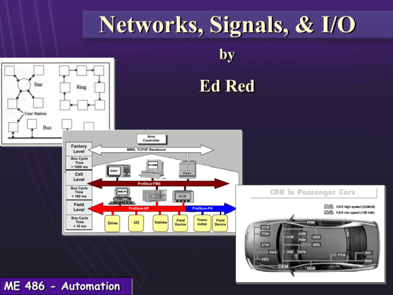
Networks
Computers in a factory use
Local Area Networks (LAN's),
ranging from feet to miles, to
communicate with each other.
Devices like PLC's, CNC machines, robots, data collection devices, vision
systems, etc., communicate maintenance and monitoring data, schedules,
process programs, and I/O.
Reference site:
http://www.wmpenn.edu/PennWeb/Academic/ArtsTech/CompSci/Networks/LAN-Overview/Lanover.html
ME 486 - Automation
Network topologies
Star network - Central station handles
all communications between computer
stations.
Ring network - Stations are connected
in continuous ring, requiring that
messages be relayed between stations
until the message gets to the right station. Messages must carry a station
address.
Bus network - Consists of a single transmission line to which stations
attached. This type is used in Ethernets, and most commonly used in
factories today.
ME 486 - Automation
Network access
Star network access - central station coordinates communication
Ring and bus access - two access methods:
1) token passing
2) carrier-sensed multiple access with collision detection (CSMA/CD).
In the token method a token (code) is passed from station to station, with only those
stations knowing the code having the right to access the message. In the CSMA/CD
method each station waits until the network is clear until it sends a message. Any
failure (such as collisions with other message packets) will result in a retry.
ME 486 - Automation
Network communications
Twisted pair - Two or more copper wires twisted along length of line. Noise
susceptibility, and low bandwidth, but inexpensive. Used in phone lines,
but not usually in factory floor networks.
Coaxial Cable - One or more strands of wire shielded by outer metal shield,
then covered with insulation - high bandwidth, noise resistant, and
typically used in factory networks.
Fiber Optics - Continuous optical fibers of glass or other material which
can transmit light - high bandwidth, impervious to noise, but expensive.
Requires mode conversion between electrical mode to light mode.
Wireless – Wireless high frequency transmission of data.
ME 486 - Automation
OSI network protocol spec
1. Physical layer. This layer is concerned with the transmission of raw bits
across the network lines. It defines the data transmission rate and the
type of transmission medium.
2. Data link layer. This layer is concerned with the transfer of units of data
across the local area network. It deals with the resolution of contentions
when two devices are attempting to transmit at the same time, the size
of the units of data, detection and correction of errors in data
transmission, etc.
3. Network layer. The network layer is concerned with the routing of
packets of data from source nodes to receiving nodes throughout the
network It stores and relays data traveling between the nodes in the
network as part of this function.
ME 486 - Automation
OSI network protocol spec
4. Transport layer. This layer is responsible for the reliable delivery of data
from originating device to destination device in the network. It works
with layer 3 in order to accomplish this function.
5. Session layer. The function of the session layer is to support an orderly
dialogue between devices using the network. It deals with network
security issues, re-synchronizing the data in the event of a transmission
failure. and similar problems.
6. Presentation layer. This layer is concerned with negotiating syntax and
format for the data exchange between the sending and receiving devices.
One way of accomplishing this is to require all devices to encode data in
a common format.
ME 486 - Automation
OSI network protocol spec
7. Application layer. This layer provides the interface with the user for
specific applications. These applications deal with problems such as
transfer of files between devices, remote job entry, message handling,
access of files located at one device from another device. etc.
ME 486 - Automation
Serial communications
1 The UART: What it is and how it works
The Universal Asynchronous Receiver/Transmitter (UART) controller is the key component
of the serial communications subsystem of a computer. The UART takes bytes of data and
transmits the individual bits in a sequential fashion. At the destination, a second UART reassembles the bits into complete bytes.
Serial transmission is commonly used with modems and for non-networked communication
between computers, terminals and other devices.
Copyright © 1996 Frank Durda IV <uhclem@FreeBSD.org>, All Rights Reserved. 13 January 1996.
UART
ME 486 - Automation
UART
OSI network protocol spec
1.2 Asynchronous Serial Transmission
Asynchronous transmission allows data to be transmitted without the sender having to
send a clock signal to the receiver. Instead, the sender and receiver must agree on timing
parameters in advance and special bits are added to each word which are used to
synchronize the sending and receiving units.
When a word is given to the UART for Asynchronous transmissions, a bit called the "Start
Bit" is added to the beginning of each word that is to be transmitted. The Start Bit is used
to alert the receiver that a word of data is about to be sent, and to force the clock in the
receiver into synchronization with the clock in the transmitter. These two clocks must be
accurate enough to not have the frequency drift by more than 10% during the transmission
of the remaining bits in the word.
After the Start Bit, the individual bits of the word of data are sent, with the Least
Significant Bit (LSB) being sent first. Each bit in the transmission is transmitted for exactly
the same amount of time as all of the other bits, and the receiver “looks” at the wire at
approximately halfway through the period assigned to each bit to determine if the bit is a 1
or a 0. For example, if it takes two seconds to send each bit, the receiver will examine the
signal to determine if it is a 1 or a 0 after one second has passed, then it will wait two
seconds and then examine the value of the next bit, and so on.
ME 486 - Automation
OSI network protocol spec
1.2 Asynchronous Serial Transmission (cont)
The sender does not know when the receiver has “looked” at the value of the bit. The
sender only knows when the clock says to begin transmitting the next bit of the word.
When the entire data word has been sent, the transmitter may add a Parity Bit that the
transmitter generates. The Parity Bit may be used by the receiver to perform simple error
checking. Then at least one Stop Bit is sent by the transmitter.
When the receiver has received all of the bits in the data word, it may check for the Parity
Bits (both sender and receiver must agree on whether a Parity Bit is to be used), and then
the receiver looks for a Stop Bit. If the Stop Bit does not appear when it is supposed to, the
UART considers the entire word to be garbled and will report a Framing Error to the host
processor when the data word is read. The usual cause of a Framing Error is that the
sender and receiver clocks were not running at the same speed, or that the signal was
interrupted.
Regardless of whether the data was received correctly or not, the UART automatically
discards the Start, Parity and Stop bits. If the sender and receiver are configured
identically, these bits are not passed to the host.
If another word is ready for transmission, the Start Bit for the new word can be sent as
soon as the Stop Bit for the previous word has been sent.
Because asynchronous data is “self synchronizing”, if there is no data to transmit, the
transmission line can be idle.
ME 486 - Automation
Factory floor communication standards
MAP (Manufacturing Automation Protocol) – not used much today
GEM (Generic Equipment Model) - generalized model that describes a
recommended implementation of the SEMI Equipment Communications
Standard II [SEMATECH]. It is used in communications and control of
semiconductor manufacturing equipment, and provides a reference model
for any type of equipment. It contains functionality that can apply to most
equipment, but does not address unique requirements of specific
equipment. [SEMI E30-94]
ME 486 - Automation
Network Assessment
1.
Explain the GEM protocol.
2.
Who are some GEM vendors (Cimetrix is one) and who are some GEM users
(Motorola is one)?
3.
Who is Sematech (developed GEM spec)?
4.
Explain the Serial (RS 232, 485, etc.) protocol?
5.
What is difference between RS 232, RS 422, RS 485, etc.?
6.
Show some examples of message/packet formats using ASCII. What does ASCII
stand for?
7.
What are typical network communications limitations? What is IEEE 1394?
What is Ethernet? Can Ethernet be used as a real-time network?
8.
What are possible communication speeds in the different modes/protocols?
9.
What type of communications networks do modern machine tools and robots
use?
10. What do modern factory networks look like?
ME 486 - Automation
Programmable Logic Control (PLC)
Definition - dedicated computer for rapid processing
of simple logic instructions in a defined time.
Purpose - send and read signals that can be used to
control and monitor devices.
Process - one of scanning all the devices (sensors,
timers, etc.) in a cyclical time period.
ME 486 - Automation
PLC Control Approaches
Logic control method - This closed-loop method uses conditions
and events to signal completion of a given step, and then
triggers the execution of some other event. This is an
asynchronous method of process control, because it does not
always proceed in a constant time period.
Sequencing method - This open-loop method uses timers to
trigger the completion of one step and the beginning of the next.
This is a synchronous control method.
ME 486 - Automation
Logic Control Elements
PLC's are typically
programmed using
Boolean logic, shown
figuratively by logical
AND, OR, and NOT
gates.
ME 486 - Automation
Logic Control Elements
AND, OR, and NOT
gates are then used to
define two more logical
elements - the NAND
and NOR gates - also
shown with their truth
tables.
ME 486 - Automation
Boolean algebra
+ = “or”
ME 486 - Automation
= “and”
Ladder logic diagrams
Ladder logic diagrams display the various logic
elements (shown above) along horizontal lines
connected to two vertical ladders.
ME 486 - Automation
Ladder logic example
Suppose we want to use a programmable logic controller to handle the
control circuitry to require an assembly line to be started in low speed
If low speed
button pushed
and in high speed. The following inputs and outputs
before
permitting
operation
button
to stop line not pushed and
are
defined:
it is not running in high speed,
then start in low speed.
11 = momentary spring push button to signal to start
the line in low speed
00 = momentary spring push button to signal to switch
the line to high speed
01 = momentary spring push button to stop the line
20 = low speed load
21 = high speed load
ME 486 - Automation
Solution:
Ladder logic example
Process will mix ingredients,
first adding ingredient A until
level reaches sensor 2, then
adding ingredient B until
level reaches sensor 1. The
mix is then stirred for a
period of time, and tank is
emptied. Investigate the
control logic required.
ME 486 - Automation
Ladder logic example
How would you
write the ladder
logic for this
problem?
ME 486 - Automation
Ladder logic example
X1, X2 = sensors
S1, S2, S3 = solenoids (relays)
M = motor (relay)
T1 = tank stir period
T2 = drain period
X2
S3
S1
X1
X2
S2
X1
M
M
TMR
T1
T1
S3
S3
TMR
T2
ME 486 - Automation
Ladder logic example
Address
Low =
0000
High =
0001
Motor =
0500
Relay =
1000
ME 486 - Automation
Fieldbus I/O
Fieldbus is a generic term that describes a new digital communications
network that is being used in industry to replace the existing 4-20 mA analog
signal standard.
The network is a digital, bi-directional, multi-drop, serial-bus communication
network used to link isolated field devices, such as controllers, transducers,
actuators and sensors.
Bi-directional means it is a duplex port; the data can be transmitted in two
directions at the same time.
Multi-drop is also referred to as multi-access and it can be interpreted as a
single bus with many nodes connected to it.
Serial-bus means the data is transmitted serially according to RS232 or
RS485 protocol. Profibus uses RS485 protocol.
ME 486 - Automation
Fieldbus I/O
Most fieldbus technologies are based on the Controller Area Network (CAN) protocol
developed in the late 1980's for serial communications between automobile modules
with high resistance to noise and an ability to detect errors.
ME 486 - Automation
CAN - Controller Area Network
ISO 11898 standard
• Uses OSI two lowest layers - data link and physical layers.
• Chips embedded in the physical modules/devices, and interfaced
to physical network.
• Transmission rate can vary from 250 KB up to 1 MB (per second
understood).
• Physical layer uses differential transmission on a twisted pair
wire.
• Non-destructive bit-wise arbitration controls access to the bus.
ME 486 - Automation
CAN - Controller Area Network
ISO 11898 standard
• Messages small (at most eight data bytes) and protected by
checksum.
• No explicit address in the messages, instead, each message carries
a numeric value which controls its priority on the bus, and may
also serve as an identification of the contents of the message.
• Elaborate error handling scheme results in retransmitted messages
when they are not properly received.
• Means for isolating faults and removing faulty nodes from bus.
ME 486 - Automation
Profibus Fieldbus
Profibus is a vendor-independent, open fieldbus standard for a
wide range of applications in manufacturing, and process
automation. Devices configured by different manufacturers can
communicate without special interface adjustments. Profibus
can be used for both high-speed, time-critical data transmission
and extensive complex communication tasks.
Profibus family consists of three compatible versions:
Profibus-DP
Profibus-PA
Profibus-FMS
ME 486 - Automation
Profibus Fieldbus
Profibus-DP:
Designed for communication between automation control systems and distributed
I/O at the device level (only card used in EAAL).
Profibus-PA:
Designed for process automation….permits sensors and actuators to be connected
on one common bus.
Area
Controller
Profibus-FMS:
For communication tasks at
the cell level and can be used
for FMS services.
Factory
Level
MMS, TCP/IP Backbone
Bus Cycle
Time
< 1000 ms
Cell
Level
Profibus-FMS
Bus Cycle
Time
< 100 ms
Field
Level
ME 486 - Automation
Bus Cycle
Time
< 10 ms
Profibus-DP
Drive
I/O
Profibus-PA
Valves
Field
Device
Transmitter
Field
Device
Profibus fieldbus in EAAL
The Profibus API set is a set of C/C++ functions provided with the Synergetic
DP card software that can be embedded into a user-customizable software
interface provided with CIMServer. Once compiled and linked to make a
customized CIMServer version, CODE client processes can directly
communicate with the
CODE (Cimetrix Open Development Environment)
Profibus-DP I/O
CxGetSignal()
Profibus-DP card for I/O
Client
CxSetSignal()
Process1
…
data exchange. .
Client
Profibus-DP Card
DPM
Process2
Data Exchange
CIMServer
CIMTools
RS485
Signal
Table
I/O Modules
ME 486 - Automation
Signal File
Device Driver Interface
(read upon CIMServer startup)
User Defined Functions
Profibus API Set
CODE Functions
Configuration Blocks
Initialization Blocks
Wago I/O modules
The digital input module receives
signals from digital field devices
(sensors, etc). The physical
connection of the WAGO module is
shown. The middle two wires are for
the sensor power supply. The other
two wires are signal input/output
and signal ground.
ME 486 - Automation
I/O Assessment
1.
Who are the primary PLC vendors?
2.
What are typical costs per I/O?
3.
How fast can I/O be processed (in milli-seconds)?
4.
What are some of the newer programming interfaces?
5.
How are PLC's integrated into the control of a mechanism such as a machine
tool?
6.
How is analog I/O handled?
7.
How does the fieldbus I/O technologies compare to the conventional PLC
technologies? In costs, differences, protocol, etc.
8.
Who are primary vendors of fieldbus technologies?
ME 486 - Automation

