Lab07-GL Rev. 1 - geek @ EE @ NMT
advertisement
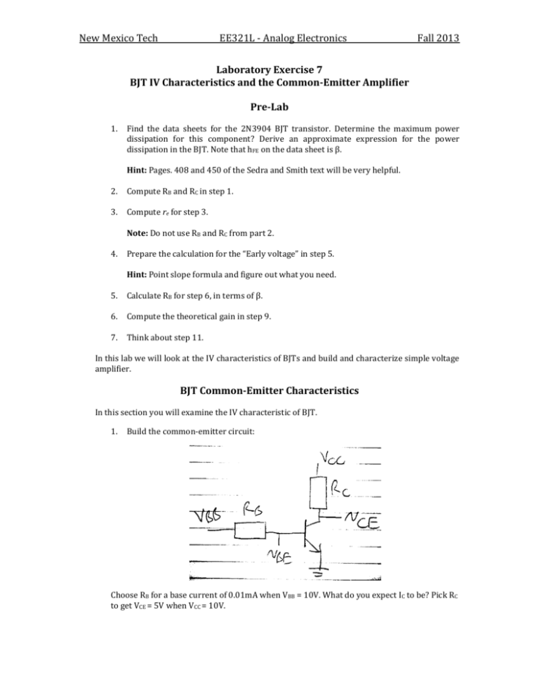
New Mexico Tech EE 321L EE321L - Analog Electronics Fall 2013 A nalog Elect r onics L abor at or y Laboratory Exercise 7 BJT IV Characteristics and theLCommon-Emitter Amplifier ab 7 B JT I V Char act er ist ics and com m on-em it t er am plifi er Pre-Lab Fall 2012 P rBJT e-Ltransistor. ab Find the data sheets for the 2N3904 Determine the maximum power dissipation for this component? Derive an approximate expression for the power in the BJT. that hFE on the2N3906 data sheet is β.transistors. What is t hemaximum Find dissipation t hedat a sheets for Note t he 2N3904 and BJT 1. 1. power dissipat ion that this component can t olerat e? Derive an approximat e expression Hint: Pages. 408 and 450 of the Sedra and Smith text will be very helpful. for t he power dissipat ion in the BJT. Not e t hat hF E on t he dat a sheet is what we call β2.in Compute class. RB and RC in step 1. 2. Compute RBreand RC 3.in st ep 1. 3. Compute for step Note: rDo not use 3. Compute st epRB3.and RC from part 2. e for 4. Prepare calculationof fortthe step 5. 5. 4. Prepare t hethe calculation he “Early Earlyvoltage” volt ageinin st ep Point slope 5. Pick Hint: RB for st ep 6. formula and figure out what you need. 5. Calculate for stepical 6, ingain termsinofstep β. 9. 6. Compute theRtBheoret 6. Compute theoretical gain in step 9. 7. Think about the st ep 11. 7. Think about step 11. wewill will look look at IVIV characteristics ofics BJTs buildand andbuild characterize simple voltage In t In histhis lablabwe atthe t he charact erist ofand BJTs and charact erize a simple amplifier. volt age amplifier. BJT Common-Emitter Characteristics B JT com m on-em it t er char act er ist ics In this section you will examine thetIV of BJT. In t his section you will examine hecharacteristic IV charact erist ic of a BJT. 1. Build the common-emitter circuit: 1. Build t he common-emit ter circuit, choosing a current base current of when 0.01 mA VB B do = you 10 expect V. What expect IC Choose RBRfor base of 0.01mA VBB =when 10V. What IC to do be? you Pick R C B afor to get V = 5V when V = 10V. CE CC to be? Pick RC to get VCE = 5 V when VCC = 10 V. 1 New Mexico Tech EE321L - Analog Electronics Fall 2013 2. What are the actual values of IB and IC? What is β? Compare with the datasheet. What is the power dissipation in the BJT? Are you operating with in the components power dissipation limits? 3. Choose a value for RE, re << RE << RC, and again make VCE = 5v and get IB, IC, and effective β again. 4. Map iC as a function of vCE: attach VCC to the function generator outputting a largeamplitude of 10V 100 Hz sine wave. Measure vCE: with one scope probe and iC with the other by measuring across R E. Plot in XY mode. If the signal is noisy try to amplify it with an op-amp (null the circuit,) averaging on the scope, or filtering with a capacitor. Hint: pg. 400 and use a capacitor. 5. Estimate the Early Voltage from the slope of iC versus vCE. The Common-Emitter Amplifier In this section you will measure the gain and linearity of the common-emitter amplifier. 6. Using the same circuit as before, without RE, connect VCC = VBB = 10V. Pick RB such that you get IC = 5 mA (use your previously found β.) Pick RC to get VCE = 5V. 7. Measure VCE, then adjust VBB to get VCE = 5V. What is the value of β and how does it compare to what you measured in step 2? 8. Connect a function generator to the base through a large capacitor. How large should the capacitor be? It depends on the frequency of the function generator signal. Hint: Use a .1μF. 9. Connect AC coupled probes to input, vB, and the output, vC. Plot the AC input, vb, and output, vC, together for the smallest input amplitude you can get and compare with a theoretical prediction. 10. Measure the gain for a few increasingly larger amplitude inputs up to the point of clipping and conclude something about the linearity of the gain with input amplitude. You can also plot output versus input in XY mode. 11. Explain what causes the clipping at the top and bottom of the curve by increasing the amplitude to have clipping about 50% of the time and plotting vBE and vCE with vC. Not So Mysterious Challenge # 7: Define and describe the origin of the following terms with respect to the physics/electrical engineering discipline: Resistance, Voltage, Current, Capacitance and Inductance. Hint: Tell me who discovered/defined each of these terms and describe how they are scientifically/officially defined. NIST may be helpful.
