steel pays off for payroll producer
advertisement
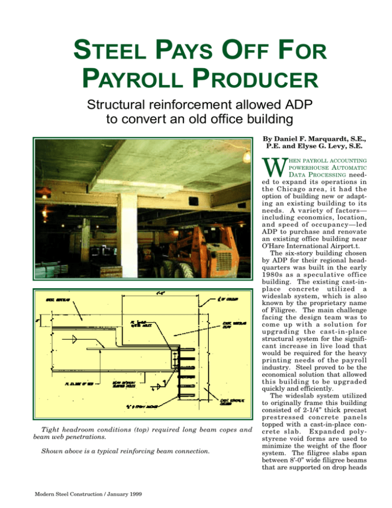
STEEL PAYS OFF FOR PAYROLL PRODUCER Structural reinforcement allowed ADP to convert an old office building By Daniel F. Marquardt, S.E., P.E. and Elyse G. Levy, S.E. W HEN PAYROLL ACCOUNTING POWERHOUSE AUTOMATIC DATA PROCESSING need- Tight headroom conditions (top) required long beam copes and beam web penetrations. Shown above is a typical reinforcing beam connection. Modern Steel Construction / January 1999 ed to expand its operations in the Chicago area, it had the option of building new or adapting an existing building to its needs. A variety of factors— including economics, location, and speed of occupancy—led ADP to purchase and renovate an existing office building near O’Hare International Airport.t. The six-story building chosen by ADP for their regional headquarters was built in the early 1980s as a speculative office building. The existing cast-inplace concrete utilized a wideslab system, which is also known by the proprietary name of Filigree. The main challenge facing the design team was to come up with a solution for upgrading the cast-in-place structural system for the significant increase in live load that would be required for the heavy printing needs of the payroll industry. Steel proved to be the economical solution that allowed this building to be upgraded quickly and efficiently. The wideslab system utilized to originally frame this building consisted of 2-1/4” thick precast prestressed concrete panels topped with a cast-in-place concrete slab. Expanded polystyrene void forms are used to minimize the weight of the floor system. The filigree slabs span between 8’-0” wide filigree beams that are supported on drop heads over the columns. In this case, the system allows for a typical bay size of 30’-0” by 30’-0”. The precast panels act as formwork for the site cast concrete, which is cast over the polystyrene laid on the precast and around wire trusses protruding from the slab. These trusses provide a mechanical connection between the precast and site-cast concrete, allowing them to act compositely. The prestressing strands and deformed bars in the precast act as the positive moment reinforcement for the composite system. The resulting one-way slab is a close cousin to slabs made of pan joists or hollow core precast planks. While the wideslab system was a very efficient system at its initial installation, it has virtually no capacity to accommodate modifications. EXISTING LIVE LOADS MORE THAN DOUBLED As with any renovation project, a significant amount of time was spent studying the existing structural system so that a rational approach to building modifications could be developed. While a number of buildings were built in the late ’70s and early ’80s using the wideslab system, the company that originally produced these slabs is no longer in business. The original building drawings were therefore a priceless source of information. As Structural Engineer-ofRecord for the original structure, Thornton Tomasetti Engineers was able to quickly assess the capacity of the existing structure and prepare alternative designs for reinforcing the building. The new functions required that the original design superimposed loads, consisting of a 50 psf live load and a 20 psf partition load be increased to a 125 psf live load for a large portion of the building. In the computer area, a new raised floor system and heavy equipment exceeded the original loading. In the printing areas of the building large rolls of paper weighing 1000 lbs. each are stored and subsequently moved to the print room using a forklift. Approximately 26,000 sq. ft. of floor area on two levels was upgraded to support these loads. Unlike a steel framing system, where significant capacity can be easily added to the structure, reinforcement of one-way concrete slabs requires considerably more effort. Several approaches were used to design the steel framing that was utilized to reinforce the floor system. Framing members needed to be located such that the existing floor slab and rein- Shown at top is a view of Automatic Data Processings new Chicago headquarters. The existing piping in the facility (above) resulted in a double-girder condition. Modern Steel Construction / January 1999 forcement would be adequate for the new loadings. Two members, located at approximately the third points of the slab were introduced to create a three span condition that could support the upgraded load. These steel beams were in turn supported on girders parallel to the slab span that were bolted to the existing cast-in-place concrete columns. These girders were designed to be mounted flush to the surface of the underside of the slab. Keeping the steel framing as high as possible was a requirement to maintain adequate headroom in the floors below the reinforcing. This required large copes in the girders at the 8’-0” square drop panels. Installation diagram for typical slab reinforcing beam ITERATIVE ANALYSIS Strength and serviceability checks were performed to analyze the new system. The initial assumption for sizing the steel was to design the new members to support the full live load. The amount of live load that will actually load the steel, however, depends upon its relative stiffness to the concrete framing system. Realizing this, an iterative analysis was performed to select steel sections that would be stiff enough to attract the proportionate loads, have adequate strength to support the loads, and would maintain adequate headroom clearance. After the iterative analyses were completed, the existing system was reviewed to determine adequacy to support the loads remaining in the concrete framing. The reinforcing system selected included heavy 21”-deep beams dividing the 30’-0” bays into three spans, with heavy 24”-deep girders on each column line. In all, 85 tons of steel was added to the building. All of the new steel framing was fireproofed after installation using a spray-on fireproofing. The installation of the beams and girders required special detailing. To ensure that the steel would see its share of the load, shims were wedged between the top flanges and the underside of the slab to force the steel to carry some of the dead load of the concrete. Specific instructions were given to prevent stress reversals in the existing slabs. After the shims were installed, the beams were anchored to the slab at thirdpoints to cut down on the unbraced beam lengths. To minimize the amount of grouting required between the steel and the slabs, the girders were installed with their natural camber downwards to follow the deflected shape of the existing slab as closely as possible. These girders were connected to the concrete columns using drilled-in epoxy anchors. Once the connection plates were anchored to the columns, the steel was lifted into place using scissors type lifts, and then welded to the shear tabs. BEAM PENETRATIONS While the basic framing system looks simple in plan, there are many complex detailing issues, such as beam penetrations, copes, and connections. Due to the added steel framing and the clear headroom requirements, mechanical and plumbing systems were run through the beams, requiring numerous beam penetrations. Using AISC’s Webopen software, a grid work of openings was established to provide flexibility in locating the mechanical system while minimizing the need for reinforcement for the steel framing. While not all of the penetrations are used, this proactive design meant that the penetrations could be made during the shop fabrication process, resulting in a net savings for the project. Close coordination was required between the Architect for the project, Chicago-based Valerio Dewalt Train, and the engineering team to insure that all of the services could fit in the construction envelope and that adequate headroom could be maintained. Because of a variety of existing conditions ranging from atypically deep concrete beams to roof drain piping, there are a handful of unique connection details. Many of these details were developed in conjunction with the steel fabricator and the general contractor, Chicagobased Pepper Construction Company. Within the computer and print room areas, a new freight elevator was added to the building. Here, steel beams served to header off the slab at the new shaft openings. Details developed for the computer and print room areas were used in modified form in other areas of the building as well. Where existing mechanical shafts had to be filled in and where new mechanical openings had to be cut, it was not permissible to erect an entire bay of framing. Other solutions for these relatively lightly loaded beams included bolting to the vertical faces of the wideslab girders and hanging steel from new mechanical support framing at the roof. Non-destructive testing methods were utilized to locate existing prestressing strands prior to starting demolition. To avoid having to reinforce areas of the building such as the first floor slab under the new cafeteria, much attention was paid to the location of new open- The new elevator shaft opening reveals the cross-section of the existing wideslab floor. ings through the existing floor slab. Parameters were given to minimize the number of prestressing strands that had to be cut, and to keep as many of the necessary cores as possible out of the middle third of the. To avoid cutting the prestressing strands, the concrete was sounded and the locations of the strands were marked on the slab prior to demolition. In addition to dunnage for new mechanical units, steel was used for a couple of other new programming requirements. To shield the new mechanical units from view, it was necessary to erect a screen wall, which was designed primarily to resist wind loads. At the truck dock, a new steel-framed canopy was erected to protect payrolls and personnel from the effects of the weather. Despite the many challenges the design team faced, the design and construction for the project was completed in less than one year. Thanks to the design flexibility of steel, Automatic Data Processing has been able to improve its working environment without the time and expense of building a new structure. Daniel F. Marquardt is a principal and Elyse G. Levy is a senior engineer with Thornton Tomasetti Engineer (TT-CBM Engineers) in Chicago.


