Management of Geotechnical Risk
advertisement
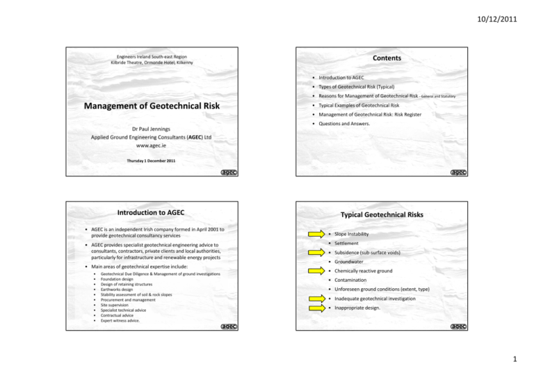
10/12/2011 Contents Engineers Ireland South‐east Region Kilbride Theatre, Ormonde Hotel, Kilkenny • Introduction to AGEC • Types of Geotechnical Risk (Typical) • Reasons for Management of Geotechnical Risk ‐ General and Statutory Management of Geotechnical Risk • Typical Examples of Geotechnical Risk • Management of Geotechnical Risk: Risk Register Dr Paul Jennings Applied Ground Engineering Consultants (AGEC) Ltd www.agec.ie • Questions and Answers. Thursday 1 December 2011 Introduction to AGEC • AGEC is an independent Irish company formed in April 2001 to provide geotechnical consultancy services • AGEC AGEC provides specialist geotechnical engineering advice to provides specialist geotechnical engineering advice to consultants, contractors, private clients and local authorities, particularly for infrastructure and renewable energy projects • Main areas of geotechnical expertise include: • • • • • • • • • • Geotechnical Due Diligence & Management of ground investigations Foundation design Design of retaining structures Earthworks design Stability assessment of soil & rock slopes Procurement and management Site supervision Specialist technical advice Contractual advice Expert witness advice. Typical Geotechnical Risks • Slope Instability • Settlement • Subsidence (sub‐surface voids) • Groundwater • Chemically reactive ground • Contamination • Unforeseen ground conditions (extent, type) f d di i ( ) • Inadequate geotechnical investigation • Inappropriate design. 1 10/12/2011 Reasons for Management of Geotechnical Risk ‐ General Reasons for Management of Geotechnical Risk Health and safety, environment, quality, programme and cost • Ground conditions are always uncertain • Compliance with standards reduces ground risk but does not eliminate ground risk • Ground related risk generally have a significant impact ‐ Highly variable nature of the ground ‐ Soil/rock mechanics engineering is good but accuracy can be poor ‐ Multiple hazards (shear failure, deformation, groundwater, chemically reactive, obstruction, etc) ‐ Unforeseen ground conditions in early stages of works (delays following works) In ncrease project cost and d delay ‐ Total Increase in Construction n Cost (%) 100 • Ground related risks affect and influence many parts of a project 80 60 Typical upper bound 40 20 0 0 1 2 3 4 5 6 7 8 9 10 11 Ground Investigation Cost/Tender Construction Cost (%) 12 Reduced cost on geotechnical studies Source: UK Highways Agency projects (1994) Reasons for Management of Geotechnical Risk – Statutory Framework (PSDP) Reasons for Management of Geotechnical Risk ‐ Statutory Framework (Designer) • Under Safety, Health and Welfare Regulations (1) there is a requirement to appoint a Project Supervisor Design Process (PSDP) • Duties of PSDP with respect to risk/hazard management: D ti f PSDP ith t t i k/h d t • Under Safety, Health and Welfare Regulations (1) the designer has defined duties • Duties of designer with respect to risk/hazard management: D i fd i ih i k/h d – Identify hazards arising from the design/technical/organisational/planning/time related aspects of the project – Where possible eliminate the hazards or reduce the risk – Communicate necessary control measures, design assumptions, or remaining risks to the PSCS (so they can be dealt with in the S&H Plan) – Prepare S&H plan for any project where there is a Particular Risk(2) (or construction takes >500 person days or 30 working days) – Role extends beyond design stage in temporary works during construction • Other duties of PSDP: – – – – Organise co‐operation between designers Prepare a safety file for the completed structure and give it to the client Notify the Authority and client of non‐compliance with any written directions issued Issue directions to designers or contractors or others – Identify any hazards that your design may present during construction and subsequent maintenance – Where possible eliminate the hazards or reduce the risk – Communicate necessary control measures, design assumptions or remaining risks to the PSDP so they can be dealt with in the S&H Plan • Other duties of designer: – – – – Co‐operate with other designers and the PSDP or PSCS Take account of any existing safety and health plan or safety file y g y p y Comply with directions issued by the PSDP or PSCS Where no PSDP has been appointed, inform the client that a PSDP must be appointed (1) Safety, Health and Welfare at Work (Construction) Regulations 2006 (S.I. No. 504 of 2006) (2) For example with respect to the ground: Schedule 1, Item 1(b) and (c) state particular risk due to (b) burial under earthfall where the risk is particularly aggravated by the nature of the work or processes used or by the environment at the place of work (1) Safety, Health and Welfare at Work (Construction ) Regulations 2006 (S.I. No. 504 of 2006) 2 10/12/2011 Slope Instability ‐ Landslides Slope Instability ‐ Landslides and Run‐out Peat Rock with thin soil cover Till (sandstone) Till (metamorphic) Slope Instability – Peat Failures Slope Instability – Peat Failures Ballincollig failure (2008) Multiple tension cracks 200m Partially detached peat raft Main debris track General slope inclination 4 degrees Temporary road construction in peat Area of worked blanket peat 3 10/12/2011 Slope Instability – Peat Failures Slope Instability – Predicting Peat Failure R314 road Glenglassera failure (1986) Deposition area/debris track General slope inclination 5 degrees 1550m Large partially detached peat raft Road layout Main debris track Headward extension into forestry Tension cracks Slope Instability Wind turbine location Hydrological/environmental buffer Slope Instability – Anecdotal Information Preliminary Stage • Identify general geotechnical conditions (eg initial walkover survey) Certain soil types more prone to instability (eg peat) • Certain soil types more prone to instability (eg peat) • Examine available landslide databases • Areas of previous failures indicate possible future failure (eg. anecdotal information) • Avoid steep ground (but peat will fail at 4 degrees!) • Avoid run‐out tracks of landslide debris (several kilometres!) g g Detailed Design Stage • Detailed walk‐over survey • Detailed ground investigation • Detailed analysis and stability assessment • Appropriate design, mitigation, zonation 4 10/12/2011 Settlement and Subsidence ‐ Karst Settlement and Subsidence – Karst Example E i ti Existing ground surface d f Soil arch eventually collapses causing subsidence at surface Drop out sinkholes form as a cavity migrates up from rockhead with time as material is carried from the soil into the limestone rock by movement of groundwater Soil Rockhead Void in limestone rock Settlement and Subsidence – Karst Example Limestone Settlement and Subsidence – Mine Collapse Example Plan of aqueduct SUBSURFACE LASER SCANNING LTD. 5 10/12/2011 Settlement and Subsidence Chemically Reactive Ground Preliminary Stage • Examine available databases (GSI karst, EPA soils maps, mining records, anecdotal information) yg / g/ g ( g • Identify general karst/mining/soft ground conditions (eg walkover survey) • Certain soil/rock types more prone to settlement/subsidence • Areas of previous subsidence indicate possible future problems • Avoid areas of high potential settlement/subsidence (may not be practical) • Associated risks – flooding, radon Detailed Design Stage • • • • Chemically reactive ground can be either: • Brown field sites (eg industrial sites, landfills) • Green field sites (eg naturally occurring) Green field sites (eg naturally occurring) Common potential issues: • Acidity (pH value) • Chlorides • Sulphates and sulphides • Industrial/domestic contamination Industrial/domestic contamination Detailed walk‐over survey Detailed ground investigation, geophysics, sub‐surface surveying Detailed analysis and assessment of settlement/subsidence Appropriate foundation design, mitigation and zonation Chemically Reactive Ground Chemically Reactive Ground Sulfides • Well known sulfide is Iron Sulfide (FeS2) or “pyrite” • Pyrite has received much press in recent years because the mineral has been found in the sub‐floor fill of damaged houses in North County Dublin • Most limestone and calcareous mudstone rocks in Dublin and neighbouring counties contain pyrite • Oxidisation of pyrite can have the following negative consequences • Groundwater can be polluted with sulfuric acid G d b ll d i h lf i id • Sulfuric acid can attack concrete and steel • Concrete may be subject to sulfate attack • Growth of expansive crystals (gypsums) heave 6 10/12/2011 Chemically Reactive Ground Chemically Reactive Ground Chemically Reactive Ground Inadequate Geotechnical Investigation Preliminary Stage • Examine available databases (GSI, EPA soils maps, historical records) • Identify general areas of reactive ground conditions (eg initial walkover survey) • Certain soil/rock types prone to producing reactive ground conditions • Anecdotal information • Areas of previous problems indicate possible future problems • Avoid areas of high potential (may not be practical) Large ‐scale peat slide Detailed Design Stage Detailed Design Stage • Detailed walk‐over survey and mapping of exposures • Detailed ground investigation including petrographic analysis • Appropriate foundation design, specification and mitigation Original: 731 GI locations (mostly probes) in 345ha site = 2 per ha Final: 5808 GI locations in 345ha site = 17 per ha 7 10/12/2011 Inappropriate Design ‐ Pit Collapse Inadequate Geotechnical Investigation • Employee killed when trial pit collapsed • Lone working in unsupported pit • Aim of geotechnical investigation: “to establish the soil, rock and groundwater conditions, to determine the properties of the soil and rock, and to gather additional relevant knowledge about the site.” • Prosecution of Employer under 2007 Corporate Manslaughter Act (UK) p y p g ( ) • Spacing and depth of ground investigation: S i d d th f di ti ti Source IS EN 1997‐2: 1997 (Eurocode 7, Part 2, Annex B3) BS5930: 1999, Code of Practice for Site Investigations, clause 12.6 Spacing Highways Agency (1997), clause 2.30 Quotation/Reference “ for high‐rise and industrial structures, a grid pattern with points at 15 m to 40 m distance” “for linear structures (roads, railways, channels, pipelines, dikes, tunnels, retaining walls), a spacing of 20 m to 200 m” “Although no hard and fast rules can be laid down, a relatively close spacing between points of exploration e.g. 10m to 30m is often appropriate for structures.” “No hard and fast rules can be given for the depth and spacing of exploratory holes. This will depend on the specific circumstances of each site and the amount and quality of existing information. Some guidance is given in BS 5930. The selection criteria for the depth and spacing of exploratory holes should always be to ensure that sufficient information is obtained to enable the proposed works to be adequately designed.” • Type of geotechnical investigation‐ see for example IS EN 1997‐2: 1997 (Eurocode 7, Part 2) Management of Risk: Geotechnical Risk Register (GRR) Example of Geotechnical Risk Register No. Hazard Cause Potential Impact Category • GRR comprises a list of geotechnical hazards and risk control measures attached to various elements of the proposed route at any project stage (eg route selection/pre planning planning any project stage (eg route selection/pre‐planning, planning, design, construction and operation) • A subjective qualitative scale is used to define risk • Hazards are rated in terms of how likely they are to occur (the Probability) and to what degree they would affect the project (the Impact) • The degree of risk is determined by combining the probability and impact assessments: impact assessments: Risk = Probability × Impact R = P × I Clayton, CRI (2001). Managing Geotechnical Risk – Improving Productivity in UK Building and Construction. Prepared under the DETR Partners in Technology programme for the Institution of Civil Engineers. Thomas Telford, London. 1 Liquefaction of 1. High/rising tidal base of excavation waters causing liquefaction (quick conditions) of sand in Sand / subsoil mixing with water excavation base and forming liquid 2. Inadequate site investigation material. information 3 IInadequate 3. d t design d i and understanding of ground conditions 4. Improper construction 2 Escape of potential contaminated water from works into surface water channels Possible contaminants from leakages, spills or fines/suspended solids Specific Risk Rating Risk Control Measure (RCM) P I R Design Control 1. Health & Safety 2. Programme 3. Cost 1. Risk of death or injury by drowning 2. Damage to plant 3. Loss and cessation of works 2 3 6 1. Review of previous excavations in the locality and in similar ground 2. Detailed site investigation to include trial trenches to expose soils 3. Boreholes and trial pits to be taken below base of excavation 4. Specify method statement from the Contractor for working in tidal sands and check h k th thatt he h iis ffully ll cognisant i t with ith ground d conditions 5. Check of implications of over-excavation 6. Check requirement to have ballast stone available to place in base of excavation 1. Extended periods of wet weather and under-design of temporary pumping 2. Over-pumping of excavation into surface water channel. 3. Potential contamination from run-off from works 4. Potential contamination from backfill material 1. Environmental 1. Risk of contamination of surface water 3 4 12 1. Walk-over survey to identify areas where greater risk of water entering works and becoming contaminated 2. Detailed site investigation to include trial trenches to expose soils and monitoring of groundwater along route 3. Spillages from plant - addressed in environmental impact statement 4. Consider limiting the extent of works/excavation opened in sensitive areas 5. Specify method statement from contractor that clearly demonstrates their awareness of this issue 6. Identify any sensitive receivers along route 1. Carry out extensive site investigation. 2. Walk-over survey of route to identify areas of variable ground (e.g. shallow rock, till, peat/organic clay) 3. Selection of conservative design parameters to allow for variable conditions on site 4. Require detailed construction method statement that clearly demonstrates understanding of the ground conditions and risks involved 5. Monitoring and observation method proposed as part of construction controls 1. Carry out extensive site investigation 2. Walkover survey of route to identify areas of variable ground (e.g. shallow rock, till, peat/organic clay) 3. Detailed method statement to be prepared with respect to excavation 3 Unexpected hard obstructions in excavations, e.g. boulders, rock outcrops 1. Ground conditions differing from those indicated from site investigation 2. Inadequate site investigation information 1. Programme 2. Cost 1. Delays to works 2. Increased noise levels due to additional rock breaking requirements 4 2 8 4 Open excavations and holes filled with disturbed peat 1. Excavation works 2. Displacements and slides 3. Improper construction methods 1. Health & Safety 2. Environmental 3. Programme 4. Cost 1. Risk of death or injury from falling into excavation 2. Damage to plant 3 5 15 Construction / Operations Control Risk Rating after RCM Contingency Measures P I R 1. Site supervision staff to inspect excavation daily 2. No/limited access into excavation 3. Areas of unexpectedly deep and weak ground to be reported and await further instruction 4. Works sequenced to tides and weathered conditions 5 S 5. Supervision i i tto ensure construction t ti carried out as detailed in the method statement 6. Limited exposure of excavation base to avoid potential for base (liquefaction) failure 1. Supervision staff to be fully briefed on the ground conditions, design requirements and construction methodology 2. Supervising staff aware of weather forecasts 3. Appropriate pumping facilities to be put in place during the construction phase and silt traps/bunds constructed 4. Temporary bunds and drains to be installed as appropriate 5. Supervision to ensure construction carried out as detailed in the method statement 6. Measures to prevent contamination/clean up contamination before work continues 1 3 3 1. Stop works 2. Ballast stone to be placed in base of excavation 3. Ensure localised area made stable 1 4 4 1. Stop work 2. Environmental Manager to be notified immediately. 3. Establish if contamination includes oil / diesel 4. Identify source of contamination and solve problem immediately as per EMP. 5. Oil contaminated water to be treated prior to discharge (use oil interceptors if appropriate) 6. Excess water to be diverted into drainage channels with filtration / sedimentation as required 7. Use simple and effective filtration measures to remove particle load e.g. straw bales/terram in drainage channels 8. Sedimentation tanks to be used (and cascaded if necessary) 9. Use adjacent areas within temporary working area as natural filter in agreement with NPWS e.g. for high levels of suspended peat 10. Reserve / additional pumping facilities to be available 1. Construction personnel briefed on expected ground conditions 2. Reporting by site staff on change in ground conditions from that predicted 3. Advance notice of change in predicted ground condition to be fed to designers 4. Supervision to ensure construction carried out as detailed in the method statement 1 2 2 1. Stop works 2. Area to be assessed 3. Use rock breakers/non-explosive pre-splitting of rock using expansive grouts or similar 1. Appropriate sequencing of works 2. Supervision of works by suitably qualified person 3. Tool box talks to be carried out prior to works 4. Ensure no excavations left open or unprotected 5. Backfill to be with a suitable material 6. Supervision to ensure construction carried out as detailed in the method statement 2 3 6 1. Stop work 2. Backfill open excavations with stone 3. Over excavate disturbed peat localised area and backfill with stone 8 10/12/2011 Content of Geotechnical Risk Register (GRR) Hazard Cause Potential Impact Category Specific Risk Rating P I Risk Control Measure (RCM) R Hazards Hazard & Cause Design Control Risk Rating following RCM Construction / Operations Control P I Contingency Measures Cause Potential Impact Category Risk Control Measures (RCM) g • Design Control • Construction / Operation Control Risk Rating following RCM P × I = R Hazard R Risk Rating P × I = R Potential Impact Example List of Geotechnical Hazards 1. 1 2. 3. 4. 5. 6. 7. 7 8. 9. 10. Risk Rating Specific P I Risk Control Measure (RCM) R Design Control Risk Rating following RCM Construction / Operations Control P I Contingency Measures R Slope Instability Slope Instability Settlement Subsidence (sub‐surface voids) Groundwater Chemically reactive ground Contamination Eroding/mobile ground conditions (coastal/marine) Eroding/mobile ground conditions (coastal/marine) Unforeseen ground conditions (extent, type) Inadequate geotechnical investigation Inappropriate design Contingency Measures *Any hazard can be sub‐divided in terms of a sub‐set or geographic location Potential Impact Cause Potential Impact Category Specific Risk Rating P I Risk Control Measure (RCM) R Design Control Category: All hazards belong to one of the following categories: • • • • • Health & Safety H lth & S f t Environmental Programme Cost Quality Risk Rating following RCM Construction / Operations Control P I Contingency Measures Hazard Cause R Potential Impact Category Examples of specific hazards are as follows: • • • • Risk of injury or death (Health & Safety) Change of hydrology (Environmental) Collapse of excavation (Programme) Damage to plant (Cost) Risk Rating Specific P I Risk Control Measure (RCM) R Design Control Risk Rating following RCM Construction / Operations Control P I Contingency Measures R Probability × b bili Impact = Risk ik P × I = R Specific: 1 IMPACT (I) Hazard Risk Rating 2 3 4 5 PROBABILITY (P) PROBABILITY (P) 1 2 3 4 5 1 Negligible 1 2 3 4 5 2 Possible 2 4 6 8 10 3 Likely 3 6 9 12 15 4 Probable 4 8 12 16 20 5 Very Likely 5 10 15 20 25 IMPACT (I) 1 Very Low 2 Low Routine 3 Medium Requires Attention 4 High Unacceptable Very High 5 9 10/12/2011 Risk Control Measures Hazard Cause Potential Impact Category Risk Rating Specific P I Risk Control Measure (RCM) R Design Control Construction / Operations Control Risk Rating following RCM Risk Rating following RCM P I Contingency Measures Hazard R Cause Potential Impact Category • If the risk is deemed excessive, then Risk Control Measures (RCM) are required to lessen the risk • These can be: ¾ Design controls: eg. Detailed site investigation, locally re‐routing, micro‐siting Specific Risk Rating P I Risk Control Measure (RCM) R Design Control Construction / Operations Control Risk Rating following RCM P I Contingency Measures R • Following the applications of the Risk Control Measures, the degree of risk is again assessed • Ideally, the Risking Rating should now be tolerable ¾ Construction or operation controls: eg. Site supervision staff to inspect critical pylon locations • Risk Control Measures mitigate the Probability and/or the Impact Control & Reporting of GRR Contingency Measures Hazard Cause Potential Impact Category Specific Risk Rating P I Risk Control Measure (RCM) R Design Control Construction / Operations Control Risk Rating following RCM P I Contingency Measures • R • Contingency Measures are then considered, should the hazard occur, eg. ¾ Stop works ¾ Monitor situation • The risk register is generally a live document: as new hazards, risk control measures or contingency measures present themselves, these should be added these should be added • • The GRR is a key method of communication of risk between the various parties at different stages of the project (eg route selection pre‐planning selection, pre planning, planning, design, construction and planning design construction and operation) Geotechnical risk management should be integrated into the overall project management process Review and feedback allows continuous improvement of the risk management system 10 10/12/2011 Summary ‐ Management of Geotechnical Risk Worked Examples ‐ Peat Slide Hazard Cause Potential Impact Category Risk Rating Specific P I Risk Control Measure (RCM) R Design Control Construction / Operations Control Risk Rating following RCM P I Contingency Measures R • Ground conditions are always uncertain • Realistically, not all ground risk can be avoided or eliminated Potential Impact Hazard Peat Slide 1. Risk of death or injury by inundation 2. Environmental damage 3. Damage to persons, plant, property and livestock 4. Loss and cessation of works 5. Adjacent land affected due to peat/ground movement Risk Rating 2 × 5 = 10 • Compliance with standards reduces ground risk but does not eliminate ground risk • Ground related risk can generally have a significant impact • Management of ground risk is essential for success: Risk Control Measures (RCM) • Design Controls (list) • Construction / Operation Controls (list) Risk Rating following RCM 1 × 5 = 5 Contingency Measures ‐ allow for sufficient budget ‐ use the right managements tools ‐ employ appropriate specialists 1. Stop works 2. Use sheetpiling to stop ground movements 3. Monitor movements following installation of sheetpiles until movements have ceased 4. Reduce speed of works 5. Reduce excavation lengths prior to backfilling with stone Questions & Answers Thank You 11
