HW 08 Solutions
advertisement
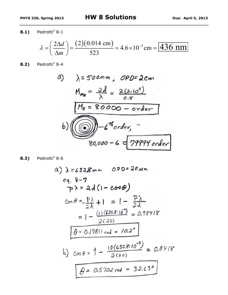
PHYS 320, Spring 2013 8.1) HW 8 Solutions Due: April 5, 2013 Pedrotti3 8-1 2d 2 0.014 cm 4.6 105 cm 523 m 8.2) Pedrotti3 8-4 8.3) Pedrotti3 8-6 436 nm PHYS 320, Spring 2013 8.4) Pedrotti3 8-8 8.5) Pedrotti3 8-10 HW 8 Solutions Due: April 5, 2013 PHYS 320, Spring 2013 8.6) Pedrotti3 8-14 HW 8 Solutions Due: April 5, 2013 PHYS 320, Spring 2013 8.7) Pedrotti3 8-19 HW 8 Solutions Due: April 5, 2013 PHYS 320, Spring 2013 8.8) HW 8 Solutions Due: April 5, 2013 Pedrotti3 8-21 Consider a light source consisting of two components with different wavelength 1 and 2. Let light from this source be incident on a scanning Fabry-Perot interferometer on nominal length d = 5 cm. Let the scaled transmittance through the length be as shown in Figure 8-20a and 8-20b. Figure 8-20b shows the first set of dual peaks of Figure 8-20a over a smaller length scale in order to allow a closer examination of the structure of the overlapping peaks. a. b. c. What is the nominal wavelength of the light source? Estimate the difference 2 1 in wavelength of the two components presuming that the overlapping transmittance peaks have the same mode number, m2 = m1 = m. Estimate the difference 2 1 in wavelength of the two components presuming that the overlapping transmittance peaks have mode numbers that differ by 1, so that m2 = m1 +1 0.002 μm Focus: Use relationship between the FabryPerot cavity length FSR and the cavity frequency FSR (and the frequency relationship to the wavelength) 0.50 μm Plan: Part c) m2 = m1 +1 2d 2d 2 1 2 1 m2 m1 2m d 2m2 d1 2 1 1 2 m1m2 d fsr 2 2d n n mn 2.0 108 μm Execute: Part a) d fsr 2 2d fsr 2 1 From Figure 8-20, d fsr 0.25 μm 2 1 0.50 μm Part b) m2 = m1 = m 2d 2d 2 1 2 1 m m 2d 2 1 2d1 1 d 1 d1 d 1 d1 50000 μm 2 1 2m1d 2 2 m1 1 d1 m1 m1 1 2m1d 2 2 m1 1 d1 m1 m1 1 2m1 d1 d 2 m1 1 d1 m1 m1 1 2m1d 2d1 m12 Now, m1 2d1 2d 2 1 2 1 d 2 d 2d 2 1 2.0 10 0.50 μm μm 2 50000 μm 2 8 2 1 2.48 106 μm Evaluate: Units are correct. PHYS 320, Spring 2013 8.9) HW 8 Solutions Due: April 5, 2013 Explain the difference between wavefront division and amplitude division in an interferometer. Give an example of each. Amplitude division: The E-field is separated b y a beam splitter such that part of the energy is directed in two directions (ex. Michelson Interferometer). Wavefront division: The wavefront is separated spatially on two locations of the wavefront, usually at an aperture stop, and those parts are superimposed to produce fringes (ex. Young’s Double Slit) 8.10) What is the difference between fringes of equal thickness and equal inclination? Equal thickness fringes – contour maps of separation between two surfaces that have an equal separation distance. Equal inclination (Haidinger) fringes are a function of the angle of inclination on surfaces formed by parallel beams from a source. Fringes are formed by rays reflected at a given angle.
