Project Identity Work Completed Left Insole Design
advertisement
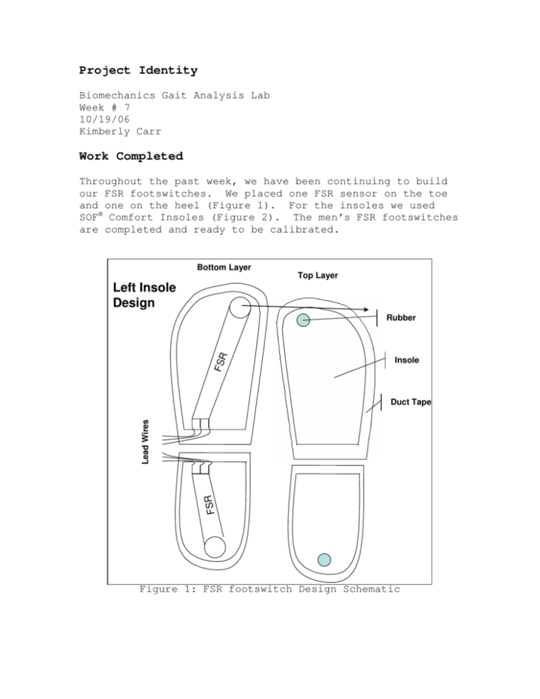
Project Identity Biomechanics Gait Analysis Lab Week # 7 10/19/06 Kimberly Carr Work Completed Throughout the past week, we have been continuing to build our FSR footswitches. We placed one FSR sensor on the toe and one on the heel (Figure 1). For the insoles we used SOF® Comfort Insoles (Figure 2). The men’s FSR footswitches are completed and ready to be calibrated. Bottom Layer Top Layer Left Insole Design FSR Rubber Insole FSR Lead Wires Duct Tape Figure 1: FSR footswitch Design Schematic Figure 2: SOF® Comfort Insoles On Thursday, September 12, 2006 we met with David Kaputa to talk about using the Tinius Olsen Testing Machine (UTM) H50KS (Figure 3) to place the 350 lbs load on the FSR sensors so that we can determine what voltage and reference resistor values we need for the drive circuit. We used a 20kΩ potentiometer in the drive circuit (Figure 4) and tested the women’s toe FSR but unfortunately, the grooves in the metal press cut through the insole and damaged the sensor before we were able to determine the correct voltage and reference resistor for the circuit. Figure 3: Tinius Olsen Testing Machine (UTM) H50KS Figure 4: Drive Circuit for FSR’s On Friday, September 13, 2006 we used thick plastic plates to sandwich the footswitch between so that the UTM does not damage anymore sensors. This technique worked well and we were able to determine that the reference resistor should be 9kΩ and the input voltage should be -5 Volts. We wanted to keep the input voltage at -5 Volts so that we can use a negative 5 volt regulator (UA7905) to convert the -9 Volts from the battery to -5 Volts. The updated ExpressSCH schematic for the 418 MHz transmission is shown in Figure 5 below. Figure 5: Schematic for 418MHz Transmission We also had to order the KH evaluation kit, 916 MHz transmitter, receiver, and antenna as well as the encoder and decoder parts from Digikey instead of from Linx Technologies because there were policy issues with the 916 MHz transmitter/receiver being sold with the KH evaluation kit. Future Work This Friday we need to determine how to analyze the data from the footswitches in LabVIEW™. We also need to test the 418 MHz transmitter and receiver assuming that we get the parts from Digikey by then. We also need to get the code template for the microprocessor so that we can perform A/D conversion. Project Review Right now we are making good progress with the FSR footswitches but we are definitely behind on the telemetry aspect of this design project and we need to put more effort into testing our circuit once our parts come in so that we can begin to design the PCB for it. Hours Worked 20 hours

