PT Activity 6.4.1: Packet Tracer Skills Integration Challenge
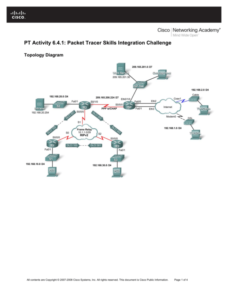
Topology Diagram
All contents are Copyright © 2007-2008 Cisco Systems, Inc. All rights reserved. This document is Cisco Public Information.
Page 1 of 4
CCNA Exploration
Accessing the WAN: Teleworker Services
PT Activity 6.4.1: Packet Tracer Skills Integration Challenge
Addressing Table
Device
Interface
IP Address
Subnet Mask
Fa0/1
192.168.10.1
255.255.255.0
S0/0/0
10.1.1.1
255.255.255.248
Fa0/1
192.168.20.1
255.255.255.0
S0/0/0
10.1.1.2
255.255.255.248
S0/1/0
209.165.200.225
255.255.255.224
Fa0/1
192.168.30.1
255.255.255.0
S0/0/0
10.1.1.3
255.255.255.248
S0/0/0
209.165.200.226
255.255.255.224
Eth0/1/0
209.165.201.1
255.255.255.224
Fa0/0
192.168.1.1
255.255.255.0
Fa0/1
192.168.2.1
255.255.255.0
PC1
NIC
192.168.10.10
255.255.255.0
PC3
NIC
192.168.30.10
255.255.255.0
Intranet
NIC
192.168.20.254
255.255.255.0
TW-DSL
NIC
192.168.1.10
255.255.255.0
TW-Cable
NIC
192.168.2.10
255.255.255.0
Web Server
NIC
209.165.201.30
255.255.255.224
Outside Host
NIC
209.165.201.10
255.255.255.224
R1
R2
R3
ISP
Learning Objectives
•
Apply basic router configurations.
•
Configure dynamic and default routing.
•
Establish teleworker services.
•
Test connectivity before ACL configuration.
•
Apply ACL policies.
•
Test connectivity after ACL configuration.
Introduction
This activity requires you to configure a default route as well as dynamic routing using RIP version 2. You
will also add broadband devices to the network. Finally, you will set up ACLs on two routers to control
network traffic. Because Packet Tracer is very specific in how it grades ACLs, you will need to configure
the ACL rules in the order given.
Task 1: Apply Basic Router Configurations
Using the information in the topology diagram and addressing table, configure the basic device
configurations on R1, R2, and R3. Hostnames are configured for you.
Include the following:
All contents are Copyright © 2007-2008 Cisco Systems, Inc. All rights reserved. This document is Cisco Public Information.
Page 2 of 4
CCNA Exploration
Accessing the WAN: Teleworker Services
•
Console and vty lines
•
Banners
•
Disable domain name lookup
•
Interface descriptions
PT Activity 6.4.1: Packet Tracer Skills Integration Challenge
Task 2: Configure Dynamic and Default Routing
Step 1. Configure default routing.
R2 needs a default route. Use the exit-interface argument in the default route configuration.
Step 2. Configure dynamic routing.
Configure RIPv2 on R1, R2, and R3 for all available networks. R2 needs to pass its default network
configuration to the other routers. Also, be sure to use the passive-interface command on all active
interfaces not used for routing.
Step 3. Check results.
Your completion percentage should be 59%. If not, click Check Results to see which required
components are not yet completed.
Task 3: Establish Teleworker Services
Step 1. Add WAN devices.
Add one DSL and one cable modem according to the topology diagram.
Step 2. Name the WAN devices.
Use the Config tab to change the display name of each WAN device to Cable and DSL, respectively.
Step 3. Connect the WAN devices.
Connect the WAN devices to their PCs and the Internet using the appropriate cables and interfaces.
Step 4. Check results.
Your completion percentage should be 86%. If not, click Check Results to see which required
components are not yet completed.
Task 4: Test Connectivity Before ACL Configuration
At this point, all branches of the topology should have connectivity. Switching between Simulation mode
and Realtime mode can speed up convergence.
Task 5: Apply ACL Policies
Step 1. Create and apply security policy number 1.
Implement the following ACL rules using ACL number 101:
1. Allow hosts on the 192.168.30.0/24 network web access to any destination
2. Allow hosts on the 192.168.30.0/24 network ICMP access to any destination.
3. Explicitly deny any other access originating from the network.
All contents are Copyright © 2007-2008 Cisco Systems, Inc. All rights reserved. This document is Cisco Public Information.
Page 3 of 4
CCNA Exploration
Accessing the WAN: Teleworker Services
PT Activity 6.4.1: Packet Tracer Skills Integration Challenge
Step 2. Create and apply security policy number 2.
Because ISP represents connectivity to the Internet, configure a named ACL called FIREWALL in the following order:
1. Allow TW-DSL web access to the Intranet server.
2. Allow TW-Cable web access to the Intranet server.
3. Allow only inbound ping replies from ISP and any source beyond ISP.
4. Allow only established TCP sessions from ISP and any source beyond ISP.
5. Explicitly block all other inbound access from ISP and any source beyond ISP.
Step 3. Check results.
Your completion percentage should be 100%. If not, click Check Results to see which required
components are not yet completed.
Task 6: Test Connectivity After ACL Configuration
Teleworkers should not be able to ping the Intranet Server, but should be able to access its HTTP server
via the web browser. Included in the activity are three PDUs, two of which should fail and one should
succeed. Check the Connectivity Tests in the Check Results menu to be sure that the completion
results are 100%.
All contents are Copyright © 2007-2008 Cisco Systems, Inc. All rights reserved. This document is Cisco Public Information.
Page 4 of 4

