New Ideas for the Use of Small Burners in the
Glass Shop, Foundry, Pottery, and Smithy
by Dudley Giberson
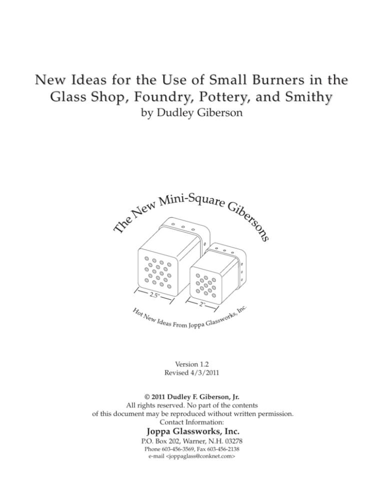
2.5"
2"
Version 1.2
Revised 4/3/2011
© 2011 Dudley F. Giberson, Jr.
All rights reserved. No part of the contents
of this document may be reproduced without written permission.
Contact Information:
Joppa Glassworks, Inc.
P.O. Box 202, Warner, N.H. 03278
Phone 603-456-3569, Fax 603-456-2138
e-mail <joppaglass@conknet.com>
New Ideas for the Use of Small Burners in the
Glass Shop, Foundry, Pottery, and Smithy
by Dudley Giberson
For many years now it has been known that a small glory hole would be of great utility in a glass shop,
something of the size of six inches and under. Many parts necessary for larger pieces of glass could easily be
made in a small glory, parts like murrine cane, bit bars, goblet stems, spiral marble cane, etc. And these could
be manufactured at a fraction of the cost of running a larger glory hole. In the history of the studio glass movement there have been a contribution toward this smallish glory called the “Murphy fire bucket,” a notoriously
low tech unit made of eight inch stovepipe with a one inch frax liner. The forced air burner is a fan attached to
an open ended pipe with no retention nozzle and this causes the problems of noise and inefficiency, not to mention the safety issue of frax blowing all over the place.
In my own practice I have attempted on several occasions to adapt my standard Giberson Ceramic
heads to this small glory purpose, especially the B-3/16 model for the the six inch glory. In my opinion this is
a poor match because the burner is nearly as large as the gloryhole it is firing. The glory opening is six inches
in diameter and the burner head exterior measures five inches in diameter in the back and four inches at the
throat. Frankly this combination is a mismatch. To boot, sometimes there are weird harmonic in these small glorys which defeated the purpose of having a helpful tool, especially since such noise would drive anyone nuts.
I had one such glory that could not be fixed, so I delivered it in its brand new condition to the landfill.
THE HEAT PATH
THE BONNET
SECTION
Ø 6.00"
THE
FIREBOX
20.5"
RIBBON
BURNER
18"
fig. 1 The rather traditional small glory hole–a six inch hole with a
slightly larger interior.
fig. 2 This is the Giberson Bead Furnace with its unusual mini ribbon burner with a combustion chamber of about 300 cubic inches.
In the early 1990s I perfected another small glory, though vertical in orientation, which I’ve written
about at length in my book, A Glassblower’s Companion, in chapter One, pages 21-24. The design is called a bead
furnace (see figure 2). It is fired with an unusual ribbon burner, frax-faced for insulation and coated with a zircon shell for durability. The head which takes about 12 hours to manufacture currently sells for $395.00. Though
a little pricey it has great thermal dynamics with an unbeatable turn down ratio (1:10). I’ve built several of these
for glassmakers all over the world. I made one for my friend Josh Simpson who uses it to manufacture the inclusions for his planet series. The firing chamber for this vertical glory is just under 300 cubic inches which is about
25% of the interior volume of the glory in figure 1. The burner system actually solves the small space/combustion problem but the burner is incredibly difficult to make. It is not financially viable: hard to make and hard to
sell. I will make one of these every once in a while for a favor. Because I felt there was a developing need for a
small space burner I pursued experimentations.
Mini-Square Giberson Burners, Page 1
The only other mini-glory experience I had was an actual model I built in 1980 as a design concept for
a large glory we were going to make at the Haystack School. The drum for this model was a piece of six inch
stove pipe that had a one inch layer of frax for insulation, pretty much like the Murphy fire bucket already mentioned. Its only saving grace was it had a very elaborate door which actually worked. The full sized glory was
going to be large, like an 18 incher, but it never came to reality. Instead I have lived with this rather quaint relic
ever since. For some years I used this four inch glory for our annual Christmas cane production, for rounding
off mini glass cane handles. The glory burner was a Ransome B-1. The problem was the metal head would melt
and need replacing every three or four weeks, but the “glory hole” part of the idea worked just fine. This was
the same problem which caused me to invent the original Giberson Ceramic Head, U. S. Patent 3697000, back
in 1968, the melting of the metal heads. But this situation was a problem of scale, like how to make a mini-burner that could fit these small spaces and provide complete combustion in, say, 150 cubic inches or less and burn
relatively quietly like the traditional Giberson Ceramic Heads. Even
this B-1 was not a good match as some of the flame burnt outside the
glory.
So this has been my December 2009 to March 2010 project, to
develop a new series of burners for this small combustion requirement. At first this was a pretty academic challenge: Could it be done?
Well, the answer is yes and they are pretty marvelous! Figure 3 is a
comparison of sizes of the original round 4” Giberson Head to the
Traditional 4"
new 2.5” Mini-Square Giberson and the 2” Mini-Square Giberson.
Giberson Head
2.5” Mini-Square
2” Mini-Square
Giberson Head
Further comparison shows the traditional round Giberson has 24
Giberson Head
holes of various sizes. The 2.5” Mini-Square has 18 holes and the 2”
fig. 3 This is a comparison of shapes between
the traditional round Giberson Head to the
Mini-Square has 13 holes. The Mini-Square series come in 7/32” or
new Mini Square Series.
3/16” holes which develop different Btu capacities (figure 4, below).
Orifice
for HP
Traditional Giberson Round Burners
New Mini-Square
Model Propane
Venturi Mix Forced Air
Btu Range Btu Range
(1000s)
(1000s)
Various Uses
No. of Holes
Hole Size
HP Propane
Nat. Gas
75
6-24
6-28
for mini-glories and furnaces (5 Tto
10 lbs.), pipe warmers, bead
furnaces, & gas annealing kilns
13
3/16"
SQ 2
7/32
72
10-34
10-40
for small foundry furnaces and glass
furnaces (5 lb) small 4-5" glories
13
7/32"
SQ 2.5
3/16
73
9-31
9-39
for small furnaces and annealers,
furnaces (5 lb) small 4-5" glories
18
3/16"
SQ 2.5
7/32
69
13-47
13-52
for small foundry furnaces and glass
furnaces (10 lb) small 5-6" glories
18
7/32"
B-3/16
65
30-68
30-75
for small glories and furnaces (25 to 35 lbs.),
pipe warmers, bead furnaces, & gas
annealing kilns
24
3/16"
B-7/32
60
39-88
39-95
pot furnaces & various multiple burner
applications
24
7/32"
B-250S
59
41-93
41-99
small to medium glories (1 cubic foot,
with 8” door), medium pot furnaces, etc.
24
1/4"
B-250
58
44-98
44-120
day tank furnaces (100 lbs.), invested
pot furnaces (150 lbs), glories (9” to 11”),
freestanding pot furnaces (200 lbs.)
24
17/64"
B-255
57
46-103
46-150
day tank furnaces (200 lbs.) & medium
glories (11” to 15”)
24
9/32"
B-650
56
54-120
54-195
large glories (16” to 18"), day tank furnaces
(to 300 lbs.), salt kilns, & forges
24
Plus one lg. ctr. hole
9/32"
5/8"
SQ 2
3/16
fig. 4 A chart of all the Giberson Ceramic Burner Heads and some suggestions for their use. The new Mini-Square series are
the first four at the top of the chart.
Mini-Square Giberson Burners, Page 2
Thoughts on the Installation of Burners
The purpose of a burner system is to provide two basic functions: 1, to properly mix and deliver the
fuel and air to the combustion chamber; and 2, to provide a platform to control the combustion so as to get
the most use out of the delivered mix (a measure of efficiency).
Mixing Tube
n
Combust
io
Cha m b e
r
Fig. 5 This is your basic mixing system schematic. The air and gas enter a mixing tube and
are delivered to the combustion chamber where they burn.
Ga
p
Fir
ed
Notice the hole at the end of the mixing tube next to the dotted line. It is a little smaller than the diameter of the mixing tube. This orifice is the retention nozzle. You see at this point, this stricture or narrowing of
the tube, the gas/air mix is forced to go faster, like at a rapids in the river, a narrower point along the regular
flow of things. The purpose of this narrowing is to keep the combustion on the other side of the dotted line. The
fact is any specific gas/air mix will burn at a calculated speed, so the speed of the mix at the exit orifice must
be greater than the burn speed, otherwise you will have burnback. Burnback is the unfortunate and sometimes
dangerous situation where the combustion is occurring within the mixing tube. Once burnback begins it is compounded by the fact that the gas/air mix expands seven times its volume when it combusts, what you might
call an explosion– BANG, BANG, POP, BANG. At this point the system is no longer working and it could cause
further problems because the gasses produced by poor combustion are carbon monoxide and particular carbon,
both of which could fill the room and cause a major explosion. So the point of the rest of this document is to
clarify what goes on around both sides of the dotted line, the place between the mixing tube and the combustion chamber.
Traditionally part of this place is called the burner block
shown in figure 6 as a black tapered block just in front of the mixing tube. Our image shows an example of what is called “gap firing,” where the air and gas are mixed and blown into the side of
a glory hole or furnace. This is typical of the old Eclispe Nozzle
Mix and it works pretty good for foundry furnaces and other
periodic heating operations where it might be on for just a small
portion of the day. This system is a big polluter of noise and heat,
those being two of the three factors of its inefficiency. The third is
the ratio of air/gas mix which changes with any change in the
back pressure of the combustion chamber, as occurs with opening
the door of a glory hole or a glass making furnace. In these situations (most glass shop applications) we prefer to close off the
fig. 6 This is the traditional gap fired burner system
source of secondary air, that is to seal off the gap between the which is filled with inefficiencies of noise, escaped
burner head and burner block thus locking in the ratio of gas/air heat, light, and poor control of the secondary air
mix presets. But as with most complicated systems this introduces caused by varying changes in back pressure in the
combustion chamber.
other problems whose solutions are best explained step by step.
Mini-Square Giberson Burners, Page 3
To begin with the shape of the burner block is really pretty important. As already mentioned the air/gas mix when it combusts
expands at a rather brisk rate to seven times its volume. If you place
this inside a straight-walled burner block you will get a slight stutter
like the corduroy of a gravel road. By tapering the burner block (at
about 12 degrees) the forces of expansion move more smoothly
toward the center of the combustion chamber. The second aspect of a
burner block is an area at the beginning where the flame can become
fig. 7 The burner block begins with parallel stabilized, where the flame pattern is set. This area needs to be somesides for setting the flame and then tapers
what narrow and short, a place where the walls are parallel to the
outward toward the combustion chamber to
flow of combustion. These characteristics are shown in figure 7 at left.
accommodate the expansion of gasses.
I have briefly passed over the rather dire necessity to make these
burners out of ceramic. Up to the time of my invention of the Giberson Ceramic Burner Head in 1968, burner
nozzles were made of iron. If you put an iron head into a glass furnace you will soon learn about the melting
point of iron which is somewhat short of your target temperature. The Giberson Tips have a melting point
somewhere near 3400˚ F. Another feature of ceramic is it is somewhat insulatory, well, more so than iron.
Another is it will not rust. I think the worst feature of iron heads is their holes will close in all by themselves,
over time, especially in an outdoor kiln setting. The one really great feature of iron heads is you can be rather
cavalier in your handling of your burners, but try
tossing a new Giberson onto the concrete floor during a fit of memory loss and you will notice this
Small Frax
Gasket
technique does not work. All systems have weak12°
nesses and strengths. Ceramic is not iron, thank
goodness! But the difficulties of ceramic can be eas3"
Open at 12˚ angle
ily overcome to produce a superior system, howevFlame
4"
Seat
er it does take planning and design.
3.5 "
The first part of this planning is for the
placement of the head in the burner block. With the
Inset
Burner in
round four inch Giberson head we found the best
Port 1/2"
installation was to inset the tip a half inch inside a
4.5” diameter burner block. The flame path goes
straight for three inches then tapers out toward the
combustion chamber at a minimum of 12 degrees fig. 8 The recommended installation of a round Giberson 4 inch tip
as shown in figure 8 to the right. (For more specific shows the specific dimensions of the components involved. The
burner block should be made of Super duty ram plastic or super duty
instructions please refer to the Joppa Glassworks castable good for 3000˚F service.
Product Catalog Spring 2008 pages 3-5).
We have already touched upon the issue of burnback (pg. 3, paragraph 2), where the air/gas mix combusts in the mixer tube. Burnback is an extremely complicated issue caused by many possible scenarios. With
glory holes and glass furnaces the main problem is heat encroachment into the interior of the burner head. You
see, any gas/air mix will have an ignition point, a given temperature which will cause ignition. The most common time for this pre-ignition (a. k. a. burnback or pop-back) to occur is just after a melt when everything is
good and hot. Things go well during the melt because the gas/air mix going through the burner system is actually cooling the interior of the burner head. But when the turn down occurs, less of this cooling gas mix is going
through the components and heat from the interior of the furnace begins moving into the burner head. At some
magical point when the interior of the head gets to 1000 degrees or so, that’s where you get pre-combustion.
Pow! Bang! Rumble, Rumble. Not fun.
The solution is to not let the inside of the head get to that problem temperature. Pop-back is not the end
of the world, but it is pretty startling at first encounter. It’s a rude experience like falling off a bicycle for the first
time, then you learn you cannot just stop without putting your foot down. To plane-off a furnace (like after a
melt) the most successful technique is to open the door and let some of the heat out (which is the object of planeing in the first place) and couple this with a lower setting for the burner and you will get no pop-back. Another
approach is to design the burner block to give us additional protection from this potential heat encroachment.
By redesigning the burner block we can eliminated the heat encroachment problem. Figure 9 shows the
Mini-Square Giberson Burners, Page 4
current state of the art burner block where we have moved the head out of the combustion tube and set it in a
shallow seat coaxially aligned with the combustion tube just in front of the flame seat. We have narrowed the
combustion tube by 1.25 inches to a diameter of 3.25 inches in the area of the flame seat. Then, like before, the
burner block tapers outward toward the combustion chamber. This arrangement is very beneficial to the burner
head because the head is exposed to easily 50% less radiant heat from the combustion chamber. The one drawback is this burner block is just slightly more technical, and thus a little more difficult to make. Later in the paper
we will discuss the manufacture of these burner blocks. All things considered this is a vast improvement.
fig. 9 This illustration shows the current state of the
art burner block to provide a much cooler environment for the burner head. Instead of being in the
combustion tube as in fig. 9 the head is placed in a
seat in front of the flame seat.
In the course of my day I get calls from all sorts of people, some highly knowledgeable and others with
hardly a clue. I had one fellow call me to complain that the burner I sold him did not function very well as it
had melted into his glass furnace. It turned out he had actually plumbed the venturi mixer and head completely
inside of the glass furnace and the cast iron had melted as did the steel backplate on the burner. It was fused
into an unrecognizable pile of metal slag with the ceramic part of the head sticking out. He actually sent me the
artifact which I placed in the outdoor museum at the top of the cullet pile. I was speechless.
I can say with some confidence that you should not duplicate that experiment.
Installation of the New Mini-Squares
The new Mini-Squares work pretty much like a regular Giberson burner only they are for small spaces.
Even so they need the same if not more care in how they are installed, and just like the above example, you cannot just put the burner into a kiln space and turn it on. It first has to be mounted properly in a mini-burner block
and then you can turn it on and go like hell.
When I was a student we did our foundry work in the old foundry which was located in the basement
of the R.I.S.D. Museum in what was truly a crawl space. We built burnout kilns using just a stack of soft brick.
In the base of the pile we built burner ports by removing a couple of bricks and into these we put the trusty old
Buzzer Burners. I think we went up to 1200˚F over three days and held it there a few hours then removed the
burners and bricked it up. In a day or so when it was all cooled off the bricks went back into boxes and we
poured bronze in the ludo molds on the basement floor. If you did that today you would be arrested as a
counter-terrorist, and the headlines would read, “Artist threatens priceless objects in museum with conflagration in basement.”
Mini-Square Giberson Burners, Page 5
In those times the art world was a “seat of the pants” operation. We just threw things together and used
them for a short while and “poof” onto something else. We would often build a glass furnace in a couple of
days, cut a 4-1/2 inch hole in the top and put the ceramic part of the burner in there and turn it on. I don’t know
how we got things to work. Some things work and other things work better. Basically we went with the better
ideas down the line. Now looking back we have a pile of rules which hopefully eliminate all the sore spots. The
point is these new Mini-Squares are not designed for just tossing into a hole in the wall of a kiln like we did
with the old Buzzer Burners. They would work that way, in a way, but they will work a lot better if you build
a burner block as per directions.
Figure 10 is a sectional drawing of the new 2” Mini-Square and its mated burner block in the wall of a
kiln shown in Figure 11 which is an isometric view of the burner installation. Notice the mixer is supported with
a solid attachment to the frame of the kiln (x).
fig. 10 A sectional view through the burner block of the
kiln shown in fig. 11. The recessed square seat on the
input end of the burner block mates with the front of
the burner and aligns the holes in the burner with the
combustion tube. The flame travels toward the combustion chamber for a distance of 1.25” then tapers outward to accommodate the expanding gasses.
fig. 11 A small kiln or furnace showing a typical
arrangement of a Ransome V100 venturi mixer
mated with a 2” Mini-Square Giberson. Notice the
rather simple bracket made from 16 gauge sheet
metal to hold the burner system in place (x).
Making the Burner Block
Each piece of equipment is unique and will undoubtedly
require you to make a slightly different mold. You can either
cast them with castable or ram them using plastic refractory. I
prefer to make ram castings. In the next few paragraphs I go
1.13"
through the process for making molds for each method.
2.50"
2.50"
168°
First, the ramming process: I use pine boards to make my
molds and I suggest using a table saw and a band saw for this
0.50"
project, though you could certainly cut all the parts with a jig
3.00"
saw or for that matter a hand saw would work. The sectional
drawing in figure 12 shows the general gist for the project. Cut
the mold parts and screw them together and leave the wood
5.00"
untreated. There are many suitable super duty ram plastics
fig. 12 Sectional drawing of the burner block mold. available that will work fine. However, I recommend Super-G
Dimensions shown are in inches. The mold parts are Ram Plastic, a 3000 degree AP Green product. Be sure to get
made of simple untreated wood. A damp plastic ceram“heat-set” that way it can sit around for years in the dry condiic, Super G 3000, is tamped into the mold to shape the
tion and all you have to do is pour a little water on it to reconcasting.
dition it and it is ready to use. Once you tamp the plastic into
the form it should be knocked loose and set to dry. While it’s in the plastic state be sure to check the “Burner
Seat Area” for clearance with the burner face. You need a tenth of an inch space on both sides. Once dry I fire
my castings to about 1800˚F to give them a bisque strength. Sometimes these things shrink a little in the process.
One block I made was a little tight so I trimmed it out with the diamond saw.
0.75"
2.02"
Burner Seat Area
Mini-Square Giberson Burners, Page 6
The Progression of a Ram Casting
Fill with Ram Plastic
fig. 13 A series of images showing the progression of a ram casting, numerically labeled: 13-1 is a sectional drawing of the burner block mold shown in figure 12. The “X” shows the target area
for filling with the ram plastic material. I recommend using
Super G 3000, an AP Green product. 13-2 shows the plastic mix
filled up to the upper dotted line (in fig 13-1). 13-3 shows the
mold entirely full. In 13-4 the mold sections are being removed
which continues in 13-5. In 13-6 we see the tapered center core
being popped out. Figure 13-7 and 13-8 are the completed burner block, front and back respectively.
fig. 13-1
fig. 13-5
fig. 13-2
fig. 13-3
fig. 13-4
fig. 13-6
fig. 13-7
fig. 13-8
Again to reiterate a somewhat subtle point: ram castings are made with a relatively stiff plastic clay that
gets packed into a wooden mold form. Within a few minutes of ramming you should de-mold the casting which
entails removing the mold parts, then place the casting in a warm place to dry. While it is still slightly pliable
make sure the recessed area shown in figure 13-8 (also identified as the “burner seat area” in figure 12) has a bit
of spare room so the burner head won’t bind there if it shrinks a little there during firing. Once fired the rest of
the construction project can proceed.
Mini-Square Giberson Burners, Page 7
The Second Method: Casting a Burner Block
Using Castable Refractory (Mizzou, Greencast, etc.)
Some craftsmen would much prefer to cast their burner blocks using refractory castables, a process
capable of reproducing delicate dimension requirements with minimal shrinkage, a process similar to casting
Plaster of Paris or Portland Cement. The tools used for this operation are a table saw and a band saw, but really this is so low tech that you could use a hand saw and a hack saw blade to shape the styrofoam mold core
parts. The outer parts of the mold are made of pine or plywood. I prefer using a table saw to shape these outer
mold walls and casting board (see fig. 14-1). Shellac these parts using yellow shellac and when the shellac is
dry, screw them together (fig. 14-2). You will need a good mold release. I make my own using micro-crystalline
brown wax heated to 225 degrees, then stir in mineral spirits and let cool. Use a ratio of 2 parts wax to 1 part
spirits, liquid measure. Decant mixture. Paint this mold release on the inside of the mold and let dry for at least
30 minutes before casting.
Paint Wax Mold Release
on Inside Surfaces
X
fig. 14-1 These are the bottom casting board and the
four walls of our soon-to-be mold into which we will
cast a burner block.
X
fig. 14-2 Here the exterior part of the mold is screwed
together and a layer of mold release (a. k. a.. parting
agent) is applied to the inside of the mold.
Next, using a rasp and a hack saw blade, shape styrofoam for core parts a, b, & c, figure 15. Then apply
a thin layer of rubber cement to all surfaces to be joined to make the core in figure 16. Let the rubber cement
dry completely then carefully align parts and press together. This makes a great adhesion. Next attach this core
column to the casting board using two sheet rock screws up through the bottom board. The mold is ready to
cast (figure 17).
c
a
b
c
b
a
Press
Together
Attach Styrofoam Core to Base
Using Sheet Rock Screws
fig. 15 This is a kind of whittling project.
The best tool for shaping these parts is a
hack saw blade just held in the hand.
Sand paper works well too. A fine toothed
band saw works well, too. The parts can
be glued together using rubber cement.
Apply thin layer of glue to both surfaces
to be attached and let glue throughly dry.
fig. 16 Here is the stack of styrofoam
parts. After making many of these castings I have found you do not have to fear
air pockets forming under the lip of “C”,
but while casting, run a wire under the lip
to remove any possible air pocket. It will
cast just fine. Use a 3000 degree Castable
like Mizoo Castable. There are many producers of super duty castable. I currently
am using a product called Mt. Savage.
Works fine.
Mini-Square Giberson Burners, Page 8
fig. 17 Here is the final mold. The core
part of this is called a “waste mold”
because, after casting has set, the styrofoam core is dug out and destroyed. If
you want to cast several of these burner
blocks simply make several cores as
shown in figure 16. The wooden parts of
the mold, the outside parts, are rewaxed for each casting. Your finished
burner block will look like images
shown in Figure 13-7 and 13-8.
Building a Test Furnace
This is a dandy little project that is
highly adaptable to your various needs: to
build a test furnace or kiln that can help define
the parameters of your project. The idea here is
to go from the general to the particular. I used
this model to define a small foundry furnace
for pouring two or three pounds of brass.
Initially I stacked the bricks to make a 4.5 cube
interior. But when I put the crucible in the furnace I realized if it were a little larger in width
the crucible would have less flame impingement, so I simply moved the bricks to achieve
the new configuration. Then I heated it up and
poured the metal. It all worked great.
This project takes shape in figure 18
which shows a testing table (a) on which sits
the furnace floor (b) made with a layer of soft
brick (IFB). In the back we have a vertical wall
(c) and a burner block (d). For this experiment
I have built a burner stand (g) for securing the
burner in its temporary position. Also shown
are the burner components: the 2” Mini-Square
Giberson Burner (with 3/16” holes) (e),
Ransome Venturi V100 (f) w #75 orifice, with a
needle valve and gauge (h).
e
c
f
d
h
a
b
g
Fig. 18 A rudimentary testing furnace comprised of a metal platform
table (a), a furnace floor (b), the beginnings of the furnace wall (c), a
burner block (d), a 2” Mini-Square Giberson Burner (e) with Ransome
Venturi (f) held in place with a burner stand (g). Also shown is the gas
supply attached to the needle valve and gauge at (h).
4.50
0
5.0
Fig. 19 In this situation we have moved the bricks around
to fit the needs of this small crucible which will hold about
three pounds of brass. The crucible is offset to minimize
flame impingement on crucible wall.
Fig. 20 Here we place a couple of bricks on the top of the walls
and start the firing cycle. In about ten minutes the interior of
the furnace is a dull red and ready for a turn up. The little half
brick is moved to charge the crucible. When the metal is ready
to pour the top bricks are removed for easy access.
With the information we have gathered from this simple experiment we can now build a permanent
structure that embodies these particular design parameters. The beauty of this is the relative ease with which
you can manipulate the components to achieve an effect. And the final thought is you can keep the components
just as they are here. Every year or two pull your bricks out of a box, assemble your furnace and pour your
bronze– a great little kit for a serious experimenter!
Mini-Square Giberson Burners, Page 9
A n I d e a L i s t for the Application of New Mini-Squar e Giberson
Burners in the Glass Shop, Foundry, Pottery and Smithy
This is an idea list just to get the wheels rolling. The fact is these Mini-Square Giberson burners are
brand new and I have not had the time to test all of the design configurations that are below, but having been
in the equipment building trade all my life I know from experience these are solid ideas that will work for the
craftsman and will save him/her a bundle of money if used for their intended purpose. For example say you
are a prototyper and your customer wants a cast brass knob on his desk tomorrow. Fire up your mini-foundry
furnace and 30 minutes later you are pouring the metal. Poof. An hour later you’ve cleaned up the casting and
it’s in the mail.
You are a glassmaker and you are experimenting on a new series of colors, but you don’t want to spend
a fortune on the gas to melt 25 or 30 pounds of glass for each color. If you build a miniature furnace that holds
a one or two pound crucible you can achieve the exact same melt profile but at a fraction of the cost. And this
same furnace idea can serve the chemistry professor who wants to show his/her students how to melt glass. By
using a miniature furnace as shown in figure 20 you can successfully demonstrate the glass melting process.
Once you have the burner system the cost is minimal: a few bricks, a crucible and a BBQ grill size propane tank
which will last several days.
This same approach can apply to a potter. For example you are having a glaze problem but it will cost
you a fortune and a lot of time to fire your big kiln. Build yourself a miniature test kiln that will deliver the same
gas fired profile as your big kiln only here it will only take a couple of hours to make your samples and at most
a gallon of propane to get your test results. This will allow you to solve countless problems that can not be
solved using an electric kiln.
One glass maker lives on top of a mountain and is off the grid. Though he has solar power his annealer uses up all his capacity. By using a Mini-Square Giberson he can gas fire his annealer for part of the cycle to
augment his limited electric power.
Outline: Uses for the Mini-Square Giberson Burners
I. Glass Shop
A. Miniature Melt Furnace
1. Solve technical formulary problems
2. Demonstrate the principles of glassmaking
B. Gloryhole Designs
1. Make a 6” studio workhorse for making fancy parts
2. Make a 4-5” for specific production work
3. Small glory for end of gaffer’s bench
C. Annealing Kiln (portable, gas fired)
II. Pottery
A. Miniature Salt Kiln
B. Miniature Gas Fired Kiln like 1 to 2 cubic feet
1. For Solving technical glaze problems
2. For specific production work like porcelain doll’s heads, hands, etc.
III. Foundry
A. Miniature Foundry Furnace (for casting 1-10 lbs Bronze)
B. Small burnout kiln, like shell molding de-waxer
1. Used for Main burner
2. Used in Smokeless afterburner situation for small stack
IV. Smithy (like in a small gas forge)
i
ng
on
Us
s
Please see the companion document called:
Th
eN
e w M i n i - S q u a re G
ibe
rs
Mini-Square Giberson Burners, Page 10
Components For Sale:
Related Items for Sale
1. Mini Square Giberson Burner Head (4 Models)–
$135 to $115
2. Burner Block– 2 Models – $35 & $30
3. Burner Stand– $65
4. V100 Ransome Venturi Mixer– $99
5. 0–30 P.S.I. Gauge– $15
6. Needle Valve– $18
7. IFB 2600°F Soft Brick $7.50 ea.
Image of Items
Description
Price
2–1⁄2 Inch Mini Square Giberson Burners, Two models:
left image:
SQ 2.5 (18 HOLES 7/32)
right image:
SQ 2.5 (18 HOLES 3/16)
$135.00 ea
2 Inch Mini Square Giberson Burners, Two models:
left image:
SQ 2 (13 HOLES 7/32)
right image:
SQ 2 (13 HOLES 3/16)
$115.00 ea
The 2-1/2” Mini Square Kit includes one 2-1/2” Mini-Square
$249.50
Giberson Burner Head ($135), a Ransome V100 Venturi Mixer ($99), Needle
Valve ($18), and a Gauge (0-30 psi $15.00), a total value of $267.00. You save $17.00
The 2” Mini Square Kit includes one 2” Mini-Square
$235.00
Giberson Burner Head ($115), a Ransome V100 Venturi Mixer ($99), Needle
Valve ($18), and a Gauge (0-30 psi $15.00), a total value $247.00. You save $12.00
This is the Ransome V100 Venturi, an Air/Gas Mixer for high
pressure propane. This is a very high quality venturi with a nicely
machined air baffle with superior quality brass spud and orifice.
$99.00
Burner Stand at 6 Degrees . This is the type of
$65.00
burner stand used in Figure 18 of this paper. It is made of 16 gauge
sheet metal and painted gray. Fits the Ransome V100 also shown above .
Cast Mini-Square Burner Block. Made of 100%
High Grade Castable Mizoo or better 3000˚F Plus..
This is a precision casting made to fit your 2” or
2.5” Mini-Square Giberson Burner Head
4"
Crucible made of fire clay. Good for a few melts of
bronze, brass, aluminum, or glass. A great way to test
formulas or demonstrate techniques.
Fits the 2-1/2” Head $35.00
Fits the 2” Head
$30.00
$7.50 ea
2600˚F NewCastle (IFB) Insulated Fire Brick, what is called a
$7.50 ea
"straight" IFB. What you want here is a relatively decent grade
of brick. Buy Locally even though these babies mostly come from
China it will save you some shipping. Look in the yellow pages under
“refractories.” For a better price, if you want a full box (25 pieces)
call my supplier:
JACK BRENNAN, REG MGR
HUNTER REFRACTORIES, INC.
36 POPE ROAD
HOLLISTON MA 01746
1-800-429-3673
Mini-Square Giberson Burners, Page 11
JOPPA GLASSWORKS, INC.
P. O. BOX 202
WARNER, NEW HAMPSHIRE 03278
(603) 456-3569, Fax at (603) 456-2138
ORDER FORM
PLEASE PHONE, FAX, OR "SNAIL MAIL" THIS INFORMATION TO ME:
YOUR NAME
YOUR BUSINESS NAME
MAILING ADDRESS (FOR US MAIL)
YOUR STREET ADDRESS (FOR UPS)
CITY, STATE, ZIP
PHONE (BUSINESS or HOME)
MASTER CARD / VISA / or DISCOVER ACCOUNT NUMBER
_ _ _ _ / _ _ _ _ / _ _ _ _ / _ _ _ _ (EXP. DATE) _ _ / _ _ & 3 number Security Code from Back
YOUR SIGNATURE (IF USING CHARGE CARD)
X______________________
I wish to order the following:
1.
2.
3.
4.
5.
_____________________________(ITEM) $_______.____
_____________________________(ITEM) $_______.____
_____________________________(ITEM) $_______.____
_____________________________(ITEM) $_______.____
_____________________________TOTAL $_______.____
If you have any questions please call Dudley Giberson at Joppa Glassworks, Inc. (603-456-3569)
Mini-Square Giberson Burners, Page 12
Mini-Square Giberson Burners, Page 13

