ph104exp06_Oscilloscope_and_Generator_03
advertisement
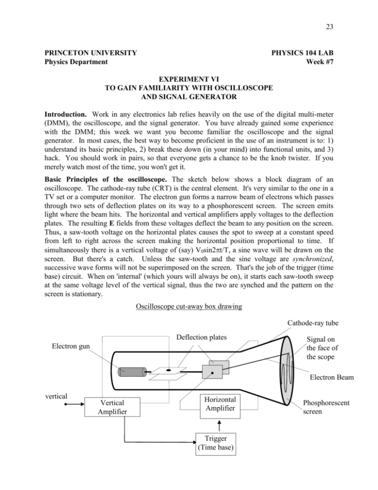
23 PRINCETON UNIVERSITY Physics Department PHYSICS 104 LAB Week #7 EXPERIMENT VI TO GAIN FAMILIARITY WITH OSCILLOSCOPE AND SIGNAL GENERATOR Introduction. Work in any electronics lab relies heavily on the use of the digital multi-meter (DMM), the oscilloscope, and the signal generator. You have already gained some experience with the DMM; this week we want you become familiar the oscilloscope and the signal generator. In most cases, the best way to become proficient in the use of an instrument is to: 1) understand its basic principles, 2) break these down (in your mind) into functional units, and 3) hack. You should work in pairs, so that everyone gets a chance to be the knob twister. If you merely watch most of the time, you won't get it. Basic Principles of the oscilloscope. The sketch below shows a block diagram of an oscilloscope. The cathode-ray tube (CRT) is the central element. It's very similar to the one in a TV set or a computer monitor. The electron gun forms a narrow beam of electrons which passes through two sets of deflection plates on its way to a phosphorescent screen. The screen emits light where the beam hits. The horizontal and vertical amplifiers apply voltages to the deflection plates. The resulting E fields from these voltages deflect the beam to any position on the screen. Thus, a saw-tooth voltage on the horizontal plates causes the spot to sweep at a constant speed from left to right across the screen making the horizontal position proportional to time. If simultaneously there is a vertical voltage of (say) V0sin2t/T, a sine wave will be drawn on the screen. But there's a catch. Unless the saw-tooth and the sine voltage are synchronized, successive wave forms will not be superimposed on the screen. That's the job of the trigger (time base) circuit. When on 'internal' (which yours will always be on), it starts each saw-tooth sweep at the same voltage level of the vertical signal, thus the two are synched and the pattern on the screen is stationary. Oscilloscope cut-away box drawing Cathode-ray tube Deflection plates Electron gun Signal on the face of the scope Electron Beam vertical Vertical Amplifier Horizontal Amplifier Trigger (Time base) Phosphorescent screen 24 Oscilloscope Operation. If you haven't used a scope before, don't be dismayed by the density of knobs and switches on the front. Most of the time you only use a few. Ignore the rest of the controls which have been preset. You can divide the face of the oscilloscope into three functional sections, as marked on the scope. Looking from left to right there are the VERTICAL, HORIZONTAL, and TRIGGER controls. Below you will find some drawings for these sections which include ONLY the controls that you will use. You will be using a Tektronix model 2225 oscilloscope. Moves CH(annel) 1 Trace up and down the screen. This lets you look at CH 1, CH 2 or both. Adjusts the vertical scale of CH 1 (in Volts). POSITION VERTICAL 1X Sets the CH 1 input to look at AC only, AC and DC together, or grounds it. MODE CH1 BOTH CH2 CH1 VOLTS / DIV 10X PROBE 5 2 10 1 20 0.5 10 0.2 m 20 0.1 50 m m POSTION 1X CH2 VOLTS / DIV 10X PROBE 5 2 10 1 20 0.5 10 0.2 m 20 0.1 50 m m AC GND DC AC GND DC CH 1 CH 2 These controls do the same things for CH 2. Input to CH 1 HORIZONTAL Move the trace left and right on the screen TRIGGER POSITION COARSE MODE FINE P-P Auto When on P-P Auto the signal triggers automatically SEC / DIV Adjusts the horizontal scale of both channels (in seconds) ms 5 2 1 .5 .2 10 .1 20 50 50 20 .1 10 5 .2 2 .5 sec 1 X-Y .5 s SOURCE CH1 When on CH1, the scope is triggered using the timing of the signal inputted to CH1 25 Take some time and study the figures on the last page and familiarize yourself with the functions of the oscilloscope. Basic Principles of the Signal Generator. You will be using a Wavetek model 19 signal generator. The signal generator can produce periodic signals of varying frequency, amplitude, and shape. FREQUENCY RANGE Hz menu on the panel of the generator allows you to choose the frequency range for the output signal. FUNCTION menu lets you choose the shape of the wave you wish to generate. FREQUENCY (START) knob on the left of the panel can be used to vary the frequency from zero to the maximum of the selected range. (i.e. if you have chosen the 2k button on the FREQ. RANGE menu, you can use the large knob to generate waves from zero hertz to 2000 hertz). AMPLITUDE knob allows you to vary the peak to peak voltage of the output wave signal. The maximum output of the generator is 20 p-p volts. DC OFFSET knob can be used to introduce a DC level on ‘top’ of which the AC signal is generated. DISPLAY SELECT button switches the display between frequency, output voltage, and DC offset. MAIN OUT connector on the front panel is the output of the generator. You will not be using any of the other knobs or controls on the panel. The figure below shows all the knobs and the buttons you need to be familiar with in order to effectively use the generator. Display Select FREQUENCY RANGE Hz 2 20 200 2k 20k 200k 2M FUNCTION DC OFFSET AMPLITUDE MAIN OUT FREQUENCY (START) 26 Become familiar with the signal generator. Connect the ‘MAIN OUT’ of the generator to CH1 of the scope. Generate the following signals with the signal generator and then use the scope to observe them. For each signal write down the settings of the generator used to produce that signal. Also, independently measure the frequency, the peak-to-peak voltage, and the DC level (using the scope). Wave Shape Sinusoidal Sinusoidal Triangular Square Signal Frequency 1000 Hz (1 KHz) 1000000 Hz (1MHz) 50000 Hz (50 KHz) 20000 Hz (20 KHz) Signal Peak-to-peak voltage 1 Volt 5 Volts 2.5 Volts 10 Volts Signal DC level 0 Volt +1 Volt -2 Volts 0 Volts Each member of the group should test his or her ability to use the oscilloscope by attempting to find the frequency and peak-to-peak voltage set by the other group member. As always write down all your observations in your lab notebook and include any comments you might have. The Black Box. After you have spent some time with the signal generator and have become familiar with the scope, disconnect the generator from the scope and turn it off. Next turn on the demonic black box. There are 12 BNC connectors on the front panel, each with a different output signal. You don't know what they are, but your lab instructor does. Your job is to measure and record the signal characteristics of each output, sketch it, and describe it in your notebook. You should look for a DC level and one or more AC signals riding on top of the DC level. Characterize the AC signals by their shape, frequency (in hertz, kilohertz or megahertz), and peak to peak amplitude (V p-p). The AC/GND/DC switch on the scope (VERTICAL section) will be useful in finding the zero level and separating DC and AC components. Note: Make sure to record the black box number in your notebook. This number is found on the top left of the black box face.
