Lab 6 help
advertisement
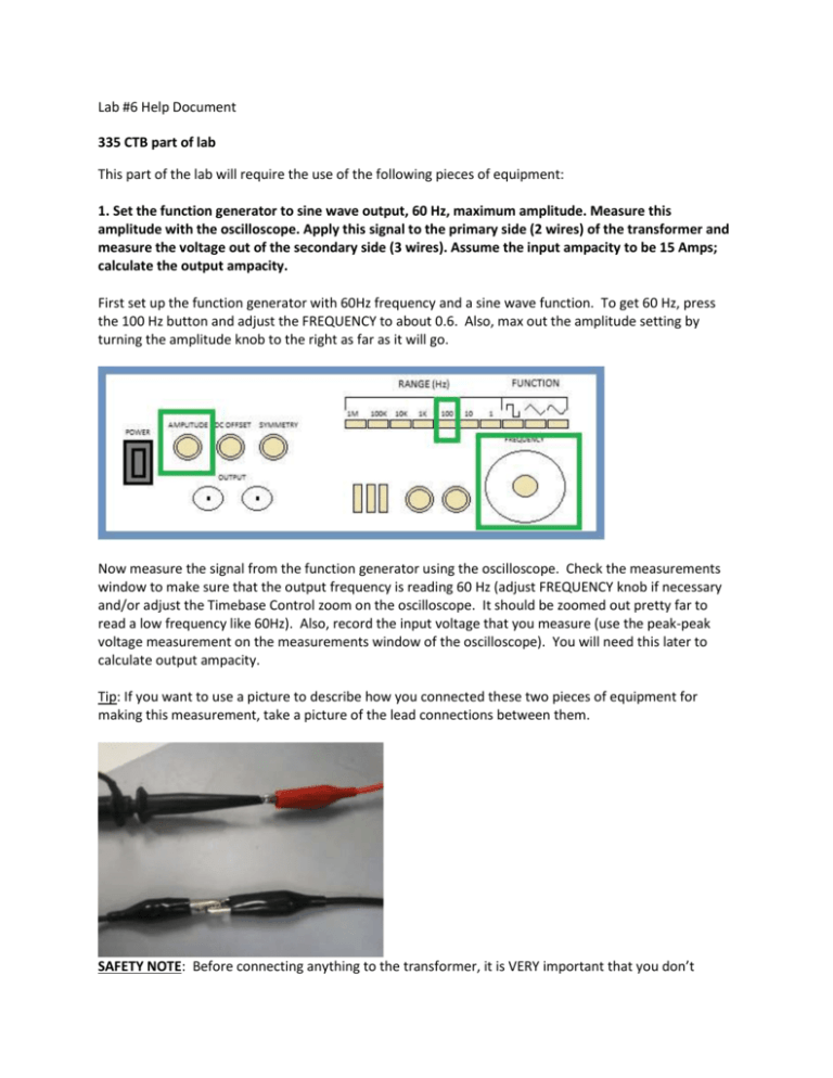
Lab #6 Help Document 335 CTB part of lab This part of the lab will require the use of the following pieces of equipment: 1. Set the function generator to sine wave output, 60 Hz, maximum amplitude. Measure this amplitude with the oscilloscope. Apply this signal to the primary side (2 wires) of the transformer and measure the voltage out of the secondary side (3 wires). Assume the input ampacity to be 15 Amps; calculate the output ampacity. First set up the function generator with 60Hz frequency and a sine wave function. To get 60 Hz, press the 100 Hz button and adjust the FREQUENCY to about 0.6. Also, max out the amplitude setting by turning the amplitude knob to the right as far as it will go. Now measure the signal from the function generator using the oscilloscope. Check the measurements window to make sure that the output frequency is reading 60 Hz (adjust FREQUENCY knob if necessary and/or adjust the Timebase Control zoom on the oscilloscope. It should be zoomed out pretty far to read a low frequency like 60Hz). Also, record the input voltage that you measure (use the peak-peak voltage measurement on the measurements window of the oscilloscope). You will need this later to calculate output ampacity. Tip: If you want to use a picture to describe how you connected these two pieces of equipment for making this measurement, take a picture of the lead connections between them. SAFETY NOTE: Before connecting anything to the transformer, it is VERY important that you don’t connect the function generator to the secondary side (side with 3 wires) for this part of the lab because it will step up the voltage if you do. Since the voltage is around 20V on the input, the output will be around 50 or more volts at around 4-5 amps which has the potential to electrocute and kill you (it only takes about 100 mA to make you lose muscle control). That being said, 50 volts and less is usually safe regardless of the current because the resistance of your skin (if dry and no lotion is applied) is enough to block 50 volts. For safety purposes however, make sure to connect the Transformer correctly. If you want to play it safe, turn off the function generator while connecting the function generator and oscilloscope leads to the transformer and then turn it back on to make a measurement. Connect the function generator to the primary side of the transformer (the side with only two wires) and the oscilloscope to the secondary side (the side with three wires. Use the two wires that are the same color and leave the middle wire disconnected). Again, for this part, do NOT wire the transformer like this: Tip: If you want to use a picture to describe how you connected the transformer to the oscilloscope and function generator, take a picture that looks like the first picture showing the correct wiring for this part of the lab. 2. Set the function generator output amplitude to 5 Vp-p, leaving it on sine wave, 60 Hz. Apply this signal to the secondary of the transformer and measure the voltage out of the primary side. Assume the input ampacity to be 15 Amps; calculate the output ampacity. Now set up the function generator with 5 V p-p leaving the frequency at 60Hz sine wave. To do this, measure the signal from the function generator using the oscilloscope. Check the measurements window to make sure that the output is 60 Hz (adjust FREQUENCY knob if necessary). Adjust the amplitude knob until the oscilloscope reads a peak-to-peak voltage of 5V. Record the input voltage that you measure (use the peak-peak voltage measurement on the measurements window of the oscilloscope). You will need this later to calculate output ampacity. Since this part is stepping up the voltage, you will need to switch the sides of the transformer that the function generator and oscilloscope are connected to. Now the function generator will be connected to the secondary side and the oscilloscope will be connected to the primary side. Again, ignore the middle wire when connecting the function generator to the secondary side (this wire will not be the same color as the other two). Make sure you do NOT wire the transformer like this for this part: It isn’t dangerous because you are decreasing voltage, but you will get an incorrect reading if you do it this way. 260 CTB part of lab These next two parts are pretty self explanatory. Just make the observations using either the microscope, magnifying glass, or both and answer the questions. (You don’t really need the microscope for these, so it would be a good idea for your TA to move these samples and the magnifying glasses and calipers to room 335 so that you guys only have to use one lab room.) To use the dial calipers, first extend them and then close them on the feature you are measuring. Make measurements using the inch side. The large numbers represent full inches, the small divisions between inches are 1/10 inches, and the analog spindle measures in 0.001 inch increments. To measure, go from biggest to smallest. Example: you read 6 as the big number, 5 as the 1/10th increment, and 43 on the analog spindle. This translates into 6.000 in + 0.5 in + 0.043 in, so 6.543 in is the total measurement.
