Chapter 4: Frequency conversion
advertisement
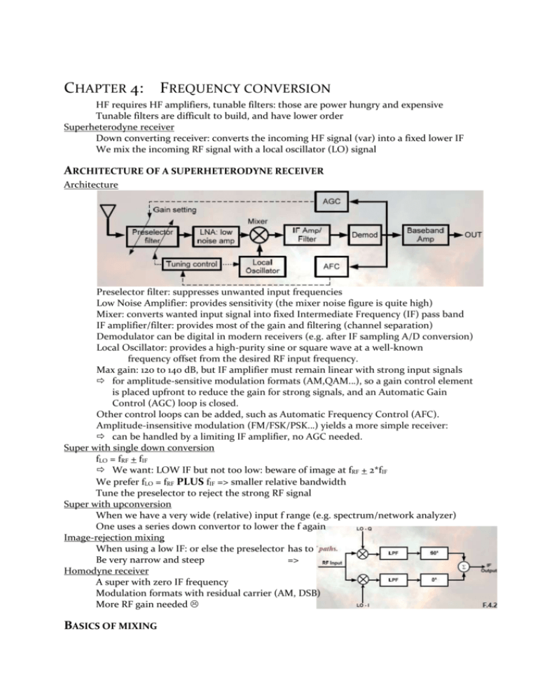
CHAPTER 4: FREQUENCY CONVERSION HF requires HF amplifiers, tunable filters: those are power hungry and expensive Tunable filters are difficult to build, and have lower order Superheterodyne receiver Down converting receiver: converts the incoming HF signal (var) into a fixed lower IF We mix the incoming RF signal with a local oscillator (LO) signal ARCHITECTURE OF A SUPERHETERODYNE RECEIVER Architecture Preselector filter: suppresses unwanted input frequencies Low Noise Amplifier: provides sensitivity (the mixer noise figure is quite high) Mixer: converts wanted input signal into fixed Intermediate Frequency (IF) pass band IF amplifier/filter: provides most of the gain and filtering (channel separation) Demodulator can be digital in modern receivers (e.g. after IF sampling A/D conversion) Local Oscillator: provides a high-purity sine or square wave at a well-known frequency offset from the desired RF input frequency. Max gain: 120 to 140 dB, but IF amplifier must remain linear with strong input signals for amplitude-sensitive modulation formats (AM,QAM…), so a gain control element is placed upfront to reduce the gain for strong signals, and an Automatic Gain Control (AGC) loop is closed. Other control loops can be added, such as Automatic Frequency Control (AFC). Amplitude-insensitive modulation (FM/FSK/PSK…) yields a more simple receiver: can be handled by a limiting IF amplifier, no AGC needed. Super with single down conversion fLO = fRF + fIF We want: LOW IF but not too low: beware of image at fRF + 2*fIF We prefer fLO = fRF PLUS fIF => smaller relative bandwidth Tune the preselector to reject the strong RF signal Super with upconversion When we have a very wide (relative) input f range (e.g. spectrum/network analyzer) One uses a series down convertor to lower the f again Image-rejection mixing When using a low IF: or else the preselector has to Be very narrow and steep => Homodyne receiver A super with zero IF frequency Modulation formats with residual carrier (AM, DSB) More RF gain needed BASICS OF MIXING Non-linearity and time-variance LTI cannot produce spectral components that are not present in the input signal(s) A mixer is nonlinear and/or time-invariant Multiplication of two sine waves in time domain => sine at sum and diff frequency Conversion gain Ratio of the IF amplitude to the incoming RF amplitude (proportional with LO level) Mixer linearity Invariability of the conversion gain Mixer isolation Caveat: LO signals are very strong, isolate them from IF and RF Physically separate ports, filter signal (or avoid spectra overlap), balanced circuits SSB vs. DSB noise figure/factor Ratio of input to output SNR (RF => IF) Mixer converts two input spectra into one IF spectrum DSB: noise figure of manufacturer SSB: Low noise receiver; LNA with low NF and enough gain High LNA gain : strong signals to be mixed => linearity Input spectrum is noisy: omit the LNA for highest linearity Passive mixer Stable, low NF but attenuate Active mixer Less LNA or IF gain needed, less noise at IF input but noisier and less linear A NON LINEAR SYSTEM AS A LINEAR MIXER Quadratic two-port as a linear mixer Perfect mixing: only 1st and 2nd order harmonics and unwanted mixing product needs to be suppressed. When using a higher LO: higher order nonlinearities arise. => Conversion gain changes Quadratic two-port FET mixer A MOSFET in long-channel regime has a quadratic characteristic. High ZL => better conversion gain Low ZL => less Miller effect = better isolation = better linearity Quadratic two-port FET mixer with source LO injection Better LO-RF isolation Same VGS but more LO power Zsource is lower => Quadratic BJT mixer Becomes => MULTIPLIER AS MIXER Better separation of RF, LO, IF Balanced mixer has a better isolation suppress even order products Switching mixers: square wave LO => tolerant for LO noise and amplitude variation Active single balance mixer M3 must be very linear: vRF to iRF Diff pair M1/M2: each takes the full tail current during half LO per. Transformer: recombines both output currents to the load Mixer transconductance Use lowest order IM = IF Port isolation Check RF->IF isolation Remove the LO signal Short LO port, without disturbing the bias High inter-port isolation Increase mixer linearity (M3) Use feedback around M3 Check LO->IF isolation Short the RF port using couple capacitors Mixer is diff amplifier for LO signal “Single balance” ACTIVE DOUBLE BALANCE MIXER Apply a second level of symmetry => we have a virtual ground! LO in parallel, IF in anti-parallel Linearization, differential RF Use inductive source degeneration Low VDD circuit LC tank is in “series” with the output=> suppresses unwanted Output frequencies Gilbert cell: 4 more linearization techniques LO input level high enough for switching with short transitions not too high can cause voltage peaks CS/E points 1. Pre-distortion Create pre-distorted RF signal: compensate for the exp BJT VBE-IC law Diode makes a log(vRF) voltage input for B3 2. Positive feedback CROSS QUAD circuit If iIN increase: M4 & M2 more I_D So a higher VGS But voltage on A and B is the same RF signal feels virtual short between A & B 3. Feed forward CASCOMP circuit: cascade diffpair M1-4 Extra diff pair M5,6 (more parasitic) 4. Piecewise linearization Diffpairs show good linearity for VB, 0, -VB More parasistics! DIODE MIXERS No DC power supply, GC < 0 dB, stable Schottky diode: Majority carrier device => fast!, low parasitics Single diode mixer VIN = RF + LO + Bias voltage Used for EHF AM envelope: drop L, use RC time constant No isolation and poor linearity Single-balance diode mixer Induce switching and one level of symmetry LO-IF isolation: short at RF = reproduced at IF RF-IF isolation: lack of symmetry no isolation Double-balance diode mixer 2nd level of symmetry LO positive => D3 & D4 conduct => ground of T1 is Reproduced at D => vRF = vIF, LO neg => vRF = -vIF LO must be higher than RF to keep diodes work Higher breakdown => put 2 or more diodes in series but requires more LO power max 5 GHz
