EC-02. Wideband Band-pass Audio Filter
advertisement
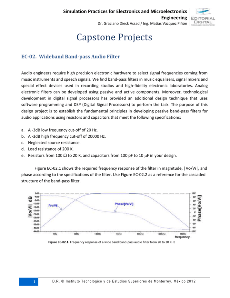
Simulation Practices for Electronics and Microelectronics Engineering Dr. Graciano Dieck Assad / Ing. Matías Vázquez Piñón Capstone Projects EC-02. Wideband Band-pass Audio Filter Audio engineers require high precision electronic hardware to select signal frequencies coming from music instruments and speech signals. We find band-pass filters in music equalizers, signal mixers and special effect devices used in recording studios and high-fidelity electronic laboratories. Analog electronic filters can be developed using passive and active components. Moreover, technological development in digital signal processors has provided an additional design technique that uses software programming and DSP (Digital Signal Processors) to perform the task. The purpose of this design project is to establish the fundamental principles in developing passive band-pass filters for audio applications using resistors and capacitors that meet the following specifications: a. b. c. d. e. A -3dB low frequency cut-off of 20 Hz. A -3dB high frequency cut-off of 20000 Hz. Neglected source resistance. Load resistance of 200 K. Resistors from 100 to 20 K, and capacitors from 100 pF to 10 F in your design. Figure EC-02.1 shows the required frequency response of the filter in magnitude, |Vo/Vi|, and phase according to the specifications of the filter. Use Figure EC-02.2 as a reference for the cascaded structure of the band-pass filter. Figure EC-02.1. Frequency response of a wide band band-pass audio filter from 20 to 20 KHz 1 D . R . © I n s t i tu t o T e c no l ó g ic o y d e E s t u d i o s S u p er i o re s d e M o n te rr e y , M é x i c o 2 0 1 2 Simulation Practices for Electronics and Microelectronics Engineering Dr. Graciano Dieck Assad / Ing. Matías Vázquez Piñón Figure EC-02.2. Cascaded modular structure for the wideband band-pass audio filter. Report. 1. Provide the circuit schematic and analytical solution of the design. 2. Describe the loading effects that the circuit may have while selecting the resistor values. 3. Include frequency domain simulation of the circuit, using an AC analysis in magnitude and phase of the transfer characteristic of the filter. 4. Include measurement of the -3dB frequency cut-offs for both 20 and 20,000 Hz frequencies. Here, you must measure magnitude and phase of the transfer characteristic. 5. Add measurement at the mid frequency, approximately at 1 KHz, of the magnitude and phase response of the filter. 6. Compare the simulated response to the analytical solution in magnitude and phase frequency responses. 7. What parameters are desirable to change if we want to change the specified cut-off frequencies? 8. Discus possible source of errors, loading effects and personal observations when performing the analysis and the simulation experiment. 9. Include references. 2 D . R . © I n s t i tu t o T e c no l ó g ic o y d e E s t u d i o s S u p er i o re s d e M o n te rr e y , M é x i c o 2 0 1 2
