Theory of Three-Phase three-wire Shunt Active Power Filter for
advertisement
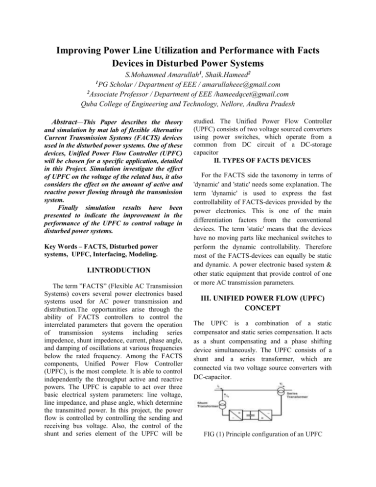
Improving Power Line Utilization and Performance with Facts Devices in Disturbed Power Systems S.Mohammed Amarullah1, Shaik.Hameed2 1PG Scholar / Department of EEE / amarullaheee@gmail.com 2Associate Professor / Department of EEE /hameedqcet@gmail.com Quba College of Engineering and Technology, Nellore, Andhra Pradesh Abstract—This Paper describes the theory and simulation by mat lab of flexible Alternative Current Transmission Systems (FACTS) devices used in the disturbed power systems. One of these devices, Unified Power Flow Controller (UPFC) will be chosen for a specific application, detailed in this Project. Simulation investigate the effect of UPFC on the voltage of the related bus, it also considers the effect on the amount of active and reactive power flowing through the transmission system. Finally simulation results have been presented to indicate the improvement in the performance of the UPFC to control voltage in disturbed power systems. Key Words – FACTS, Disturbed power systems, UPFC, Interfacing, Modeling. I.INTRODUCTION The term ”FACTS” (Flexible AC Transmission Systems) covers several power electronics based systems used for AC power transmission and distribution.The opportunities arise through the ability of FACTS controllers to control the interrelated parameters that govern the operation of transmission systems including series impedence, shunt impedence, current, phase angle, and damping of oscillations at various frequencies below the rated frequency. Among the FACTS components, Unified Power Flow Controller (UPFC), is the most complete. It is able to control independently the throughput active and reactive powers. The UPFC is capable to act over three basic electrical system parameters: line voltage, line impedance, and phase angle, which determine the transmitted power. In this project, the power flow is controlled by controlling the sending and receiving bus voltage. Also, the control of the shunt and series element of the UPFC will be studied. The Unified Power Flow Controller (UPFC) consists of two voltage sourced converters using power switches, which operate from a common from DC circuit of a DC-storage capacitor II. TYPES OF FACTS DEVICES For the FACTS side the taxonomy in terms of 'dynamic' and 'static' needs some explanation. The term 'dynamic' is used to express the fast controllability of FACTS-devices provided by the power electronics. This is one of the main differentiation factors from the conventional devices. The term 'static' means that the devices have no moving parts like mechanical switches to perform the dynamic controllability. Therefore most of the FACTS-devices can equally be static and dynamic. A power electronic based system & other static equipment that provide control of one or more AC transmission parameters. III. UNIFIED POWER FLOW (UPFC) CONCEPT The UPFC is a combination of a static compensator and static series compensation. It acts as a shunt compensating and a phase shifting device simultaneously. The UPFC consists of a shunt and a series transformer, which are connected via two voltage source converters with DC-capacitor. FIG (1) Principle configuration of an UPFC The DC-circuit allows the active power exchange between shunt and series transformer to control the phase shift of the series voltage. This setup, as shown in Figure, provides the full controllability for voltage and power flow. The series converter needs to be protected with a Thyristor bridge. Due to the high efforts for the Voltage Source Converters and the protection, an UPFC is getting quite expensive, which limits the practical applications where the voltage and power flow control is required simultaneously. Terminals of the line or power angle, were controlled separately using either mechanical or other FACTS devices such as a Static Var Compensator (SVC), a Thyristor Controlled Series Capacitor (TCSC), a phase shifter, etc. However, the UPFC allows simultaneous or independent control of these parameters with transfer from one control scheme to another in real time. Also, the UPFC can be used for voltage support, transient stability improvement and damping of low frequency power system oscillations. Because of its attractive features, modeling and controlling an UPFC have come into intensive investigation in the recent years. IV. UPFC MATHEMATICAL MODEL In order to simulate a power system that contains a UPFC, the UPFC needs to be modelled. Fig shows a diagram for UPFC; all the variables used in UPFC model are denoted in fig with bold fonts representing phasors. Per unit system and MKS units are jointly used in modelling. The ac system uses par unit system with its variables calculated based on the system-side SB and VB, while the dc variables are expressed in MKS units. We first consider the UPFC dc link capacitor charging dynamics.The current Id1, Id2 and the capacitor voltage and current have the following relation with harmonics neglected Id C dVd dt I d I d1 I d2 (1) (2) If we assume the inverters are ideal, the real power exchange with the ac system will be (P1 and P2 are in p.u.): Vd I d1 VI , P2 - d d2 SB SB P1 (3) From equation (1) and (2), we have: CCd dVd P1 P2 SB dt (4) From ac system, we know that P1 and P2 calculated by: n V V 1 P1 R e V1I1 R e V1 1 S jX 11 VS Vpq VR P2 R e Vpq I1 R e Vpq jX 12 (5) Applying modern PWM control technique two the two voltage source converters, the relations between the inverter dc-and ac-side voltages can be expressed by: V1 m1 Vd V , V2 m 2 d VB VB (6) Where coefficient m1 and m2 represent the PWM control effects in order to maintain desired inverter ac-side voltages V1 and V2 respectively. The desired m1 and m2 are UPFC main control outputs. V1 and V2 are in p.u. and VB is the ac system base voltage. The phase angle of (V1) and (V2) are denoted as (Ө1) and (Ө2) respectively. They are controlled through firing angle (φ1) and (φ2) of two converters: θ1 θs 1 , θ 2 θs 2 (7) The desired φ1 and φ2 are UPFC main control outputs. Finally, taking series transformer ratio into consideration, and rewriting equations (1) to (6), the UPFC power frequency model used in dynamic study will be: CVd dVd P1 P2 SB dt (8) Where: n V V 1 S 1 P1 R e V1 jX 11 VS Vpq VR P2 R e Vpq jX 12 (9) V1 m1 Vd V , V2 m 2 d VB VB (10) θ1 θs 1 , θ 2 θs 2 The desired m1, φ1, m2 and φ2 can be obtained from UPFC main control system, therefore based on equation (9) together with UPFC control system equations and ac network interface equation. V. INTREFACE OF UPFC TO THE AC NETWORK The interface calculation of UPFC to ac network will have significant impacts on transient stability Substituting equation (11) into equation (10), and rearranging the second equation of equation (10), we finally have: n2 n I1G I 2G YSS YRS 1 VS YSR YRR VR 1 V1 jX t1 jX t1 1 1 1 VS I 2G YRS YRR VR Vpq jX t2 jX t2 jX t2 (13) Where: YSS Y RS If we define a constant matrix: YUU FIG(2)The Interface of the UPFC to the network YSR I YUU , 1G YUG E G YRR I 2G n12 YSS YRS jX t1 1 YSR jX t2 YSR YRR 1 YRR jX t2 (14) n1 jX V1 I1G I 2G I U t1 1 Vpq I 2G jX 12 We have: In the interface calculation we assume that the bus admittance matrix has been reduced to generator internal buses with UPFC ac terminal buses remained. The corresponding reduced bus admittance matrix takes the form YGG Y UG YGU E G IG YUU VU I U (11) YUU VU I U (15) The equations from (13) to (14) are used for iteration of UPFC network interface as follows: a. STEP 1: Estimates the initials voltages of sending and receiving buses and calculate current based in equations (13) and (9). Where: EG : Generator internal voltage. IG : Generator internal current. VU : ac terminal bus voltages of the UPFC. The UPFC currents injecting to the ac network can be expressed by: b .STEP 2: Solve equation (14) for difference of the initials voltages values. If the difference is less than the given tolerance for new value of sending and receiving voltages are considered as the solution of equation (12). Otherwise go to step 3. I U1 c. STEP 3: Update initial voltages and repeat steps 1 and 2 till convergence is reached. I U2 Vs Vpq VR n1Vs V1 n1 jX t1 jX t2 Vs Vpq VR jX t2 (12) VI. SIMULATED TEST SYSTEM FIG (3) COMPLEX POWER SYSTEM VII.SIMULATION RESULTS (1) (a). without UPFC at bus 3 (b). with UPFC at bus3 Fi (1) (A) Active power & Reactive power at bus3 with out upfc (B) Active power & Reactive power at bus3 with UPFC (2) (a). without UPFC at bus 3&4 (b). with UPFC at bus 3&4 Fig (2) (A) RMS voltage at bus 3&4 with out UPFC (B) RMS voltage at bus 3&4 with UPFC (3) (a). without UPFC at bus 3&4 (5) (a). DC VOLTAGE with UPFC (b). with UPFC at bus 3&4 (b).SERIES INSERTED VOLTAGE with UPFC Fig (3) (A) Vabc & Iabc at bus 3&4 with out UPFC (B) Vabc & Iabc at bus 3&4 with UPFC (4) (a). with out UPFC at bus 4 VIII. CONCLUSION (b). with UPFC at bus 4 Fig (4) (A) Active power & Reactive power at bus4 with out UPFC (B) Active power & Reactive power at bus4 with UPFC In this project, the simulation results are obtained by Matlab are due to three phase fault in transmission lines with and with out presence of UPFC. The time of fault is from 0.3 to 0.6 as shown results. The compensation of an electrical system by using UPFC-FACTS device has been studied. Two important coordination problems have been addressed in this projectr related to UPFC control. One, the problem of real power coordination between the series and the shunt converter control system. Second, the problem of excessive UPFC bus voltage excursions during reactive power transfers requiring reactive power coordination. The simulation results, obtained by Matlab show the efficiency of UPFC, in controlling line both active and reactive power flow, three phase voltage and current , rms voltage, DC voltage. REFERENCES [1] Sadeghazadeh S.M., Ehsan M., Hajsaid N., “Application of FACTS devices for the maximum laudability improvement in transmission line”, EPE’97, Trondheim, 8-10 sept, vol.3, pp.950-955. [2] Douglas J., Heydt G.T., “ Power flow control and power flow studies for systems with FACTS devices, in IEEE transactions on power systems,vol.13,n°1,February 1998, pp. 60-65. [3] J. F. Keri, “Unified Power Flow Controller (UPFC): Modeling and analysis.” IEEE. Trans. Power Delivery, vol. 14. pp.648-654, apr.1990. [4] D. M. Divan, W. E. Brumsickle, R. S. Schneider, B. Kranz, R. W. Gascoigne, D. T. Bradshaw, M. R. Ingram, I. S. Grant, “A Distributed Static Series Compensator System for Realizing Active Power Flow Control on Existing Power Lines,” IEEE Transactions on Power Delivery, Vol. 22, No. 1, Jan 2007, p 642 - 649. [5] H. Johal, D. Divan, “Design Considerations for Series-Connected Distributed FACTS Converters,” IEEE Transactions on Industry Applications, Vol. 43, No. 6, Nov/Dec 2007, p 654 - 661. [6] D. G. Ramey, R. J. Nelson, J. Bian, T. A. Lemak, “Use of FACTS Power Flow Controllers to Enhance Transmission Transfer Limits,” Proceedings of the American Power Conference, 1994, p 712718. [7] L. Gyugyi, C. D. Schauder, K. K. Sen, “Static Synchronous Series Compensator: A Solid-State Approach to the Series Compensation of Transmission Lines,” IEEE Transactions on Power Delivery, Vol. 12, No. 1, Jan. 1997, p 406 - 417. [8] L. Gyugyi, C. D. Schauder, S. L. Williams, T. R. Rietman, D. R. Torgerson, A. Edris, “The Unified Power Flow Controller: A New Approach to Power Transmission Control,” IEEE Transactions on Power Delivery, Vol. 10, No. 2, Apr. 1995, p 1085 - 1097. [9] L. Gyugyi, “Dynamic Compensation of AC Transmission Lines by Solid-State Synchronous Voltage Sources,” IEEE Transactions on Power Delivery, Vol. 9, No. 2, Apr. 1994, p 904 - 911. [10] O. Alsac, J. Bright, M. Prais, B. Stott, “Further Developments in LP-Based Optimal Power Flow,” IEEE Transactions on Power Systems, Vol. 5, No. 3, Aug 1990, p 697 - 711. [11 ] W. F. Tinney, V. Brandwajn, S.M. Chan, “Sparse Vector Methods,” IEEE Transactions on Power Apparatus and Systems, Vol. PAS-104, No. 2, Feb 1985, 295 - 301. [12] X. R. Chen, N. C. Pahalawaththa, U. D. Annakkage, C. S. Kumble, “Controlled series compensation for improving the stability of multi-machine power systems,” IEE Proceedings: Generation, Transmission and Distribution, v 142, n 4, Jul, 1995, p 361-366.

