Case study of a belt and pulley drive system
advertisement
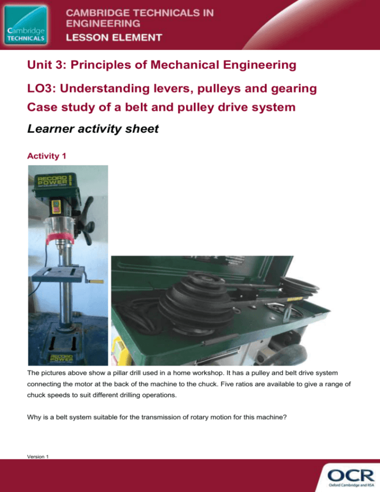
Unit 3: Principles of Mechanical Engineering LO3: Understanding levers, pulleys and gearing Case study of a belt and pulley drive system Learner activity sheet Activity 1 The pictures above show a pillar drill used in a home workshop. It has a pulley and belt drive system connecting the motor at the back of the machine to the chuck. Five ratios are available to give a range of chuck speeds to suit different drilling operations. Why is a belt system suitable for the transmission of rotary motion for this machine? Version 1 The belt used in this application is a vee-belt (ie its cross section is v shaped). What are the advantages of a vee-belt compared to other types of belt used in pulley and belt drive systems. Activity 2 The electric motor driving the system runs at 1250 rpm and the output speeds required are approximately 500 rpm to 2500 rpm, with 5 ratios in total. What diameter pulleys would you use to achieve this range of speeds? You should first think about what velocity ratios are needed to achieve the highest and lowest output speeds, and then decide on suitable intermediate ratios. The final diameters of the pulleys should take account of practical factors such as the overall size of the machine and reasonable minimum diameters to avoid damage to the belt. Is it possible to use the same diameters for both sets of pulleys (say diameters D1, D2, D3, D4 and D5)? This would mean that the highest output speed would be produced using D5 (largest) driving D1 (smallest), and the lowest output speed would be produced using D1 driving D5. Version 1


