plane 1029
advertisement
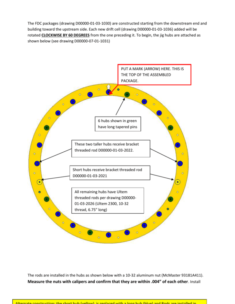
The FDC packages (drawing D00000-01-03-1030) are constructed starting from the downstream end and building toward the upstream side. Each new drift cell (drawing D00000-01-03-1036) added will be rotated CLOCKWISE BY 60 DEGREES from the one preceding it. To begin, the jig hubs are attached as shown below (see drawing D00000-07-01-1031) PUT A MARK (ARROW) HERE. THIS IS THE TOP OF THE ASSEMBLED PACKAGE. 6 hubs shown in green have long tapered pins These two taller hubs receive bracket threaded rod D00000-01-03-2022. Short hubs receive bracket threaded rod D00000-01-03-2021 All remaining hubs have Ultem threaded rods per drawing D0000001-03-2026 (Ultem 2300, 10-32 thread, 6.75” long) The rods are installed in the hubs as shown below with a 10-32 aluminum nut (McMaster 93181A411). Measure the nuts with calipers and confirm that they are within .004” of each other . Install and lightly tighten against their respective hubs. Note that the connecting strap and spacer are added at this time as well. Aluminum 10-32 nuts on all threaded rods The gusset ring D00000-01-03-2046 is to have an insulating sheet of 5 mil? thick Mylar glued to its bolting surface with Hysol ( RE2039/hd3561). This operation should either be done as a vacuum bag procedure or on the membrane tensioning fixture to insure that the Mylar is flat against the aluminum without bubbles (this would affect the final flatness). After adding this insulator, add the gusset ring to the assembly jig oriented as shown below: CUT IN GUSSET RING At this point, carefully inspect the underside of the gusset ring to insure that it is flat against the aluminum nuts. A depth micrometer can be used to check the distance from the top of the gusset ring to the surface or the thick jig plate. Fabricate and tack bond an O ring ( per procedure D00000-01-03-P0XX) into end window assembly D00000-01-03-1031 and add the end window to the jig with O ring facing up as shown below. The next item to go on the stack Is a type 3 cathode (D00000-01-03-1035, ground plane has holes). Prior to adding it to the stack, use paint markers to color code as shown below. Note that this color coding applies to this cathode and all type 2 cathodes (all downstream cathodes) Do NOT apply this pattern to the other type 3 cathode which will be added last- These marks will assist when adding the preamps to identify the correct heat clamp type (see drawing D00000-01-03-1019). All of these daughter cards to be marked with red paint marker Yellow mark here After marking the downstream type 3 cathode, add it to the stack oriented as shown below: Note daughter card orientation: The next component to be added is the wire board (D00000-01-03-1026). It is also color coded; this can be done either prior to adding to the stack or after. Mark as indicated below, and install the O ring on the back side of the wire board. Add it to the stack in the shown orientation. Note that all of the wire boards will have this same color pattern: Put red paint marks at all four preamp connectors. All wire boards will be marked with this pattern Mark added at step 1 60° The next component to add is the gas spacer D00000-01-03-1033 with two O rings installed. Orient as shown below (all Gas spacers will have this same orientation with respect to the Jig). The next component to add is a type 1 cathode (D00000-01-03-1029, no ground plane). Prior to adding the cathode, mark it with paint markers as shown below. All of the type 1 cathodes are on the “upstream end”of the package and will have this color pattern. The Type 3 cathode that will be added last will also have this pattern. All of these cards are marked with red Mark this daughter card with a white marker Mark this card with yellow paint marker Install the O ring in the cathode and add it oriented as shown below: Note that the solitary daughter card orientation The next component to be added is a type 2 cathode (D00000-01-03-1028, with a ground plane, no holes in the plane). Prior to adding it, mark it with the same pattern used on the type three cathode added at the beginning of the stack. Note that this cathode is 60 degrees clockwise from the type three cathode added previously. Now the second wire board is added after marking with the paint marker and adding its O ring as described previously: 120° Now add the second gas spacer with its O rings: Add the next type 1 cathode marked and with its O ring as previously described, in the orientation shown:


