Item Spec`s Spec`s with Sw DL3155M19R DIGITAL CIRCUITS
advertisement
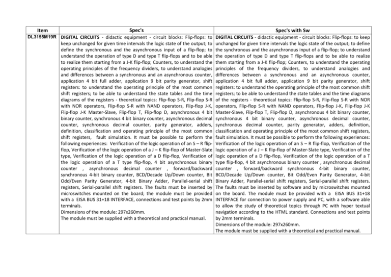
Item Spec's Spec's with Sw DL3155M19R DIGITAL CIRCUITS - didactic equipment - circuit blocks: Flip-flops: to DIGITAL CIRCUITS - didactic equipment - circuit blocks: Flip-flops: to keep keep unchanged for given time intervals the logic state of the output; to define the synchronous and the asynchronous input of a flip-flop; to understand the operation of type D and type T flip-flops and to be able to realize them starting from a J-K flip-flop; Counters, to understand the operating principles of the frequency dividers, to understand analogies and differences between a synchronous and an asynchronous counter, application 4 bit full adder, application 9 bit parity generator, shift registers: to understand the operating principle of the most common shift registers; to be able to understand the state tables and the time diagrams of the registers - theoretical topics: Flip-flop S-R, Flip-flop S-R with NOR operators, Flip-flop S-R with NAND operators, Flip-flop J-K, Flip-flop J-K Master-Slave, Flip-flop T, Flip-flop D, asynchronous 4 bit binary counter, synchronous 4 bit binary counter, asynchronous decimal counter, synchronous decimal counter, parity generator, adders, definition, classification and operating principle of the most common shift registers, fault simulation. It must be possible to perform the following experiences: Verification of the logic operation of an S – R flipflop, Verification of the logic operation of a J – K flip-flop of Master-Slate type, Verification of the logic operation of a D flip-flop, Verification of the logic operation of a T type flip-flop, 4 bit asynchronous binary counter , asynchronous decimal counter , forward/backward synchronous 4-bit binary counter, BCD/Decade Up/Down counter, Bit Odd/Even Parity Generator, 4-bit Binary Adder, Parallel-serial shift registers, Serial-parallel shift registers. The faults must be inserted by microswitches mounted on the board; the module must be provided with a EISA BUS 31+18 INTERFACE, connections and test points by 2mm terminals. Dimensions of the module: 297x260mm. The module must be supplied with a theoretical and practical manual. unchanged for given time intervals the logic state of the output; to define the synchronous and the asynchronous input of a flip-flop; to understand the operation of type D and type T flip-flops and to be able to realize them starting from a J-K flip-flop; Counters, to understand the operating principles of the frequency dividers, to understand analogies and differences between a synchronous and an asynchronous counter, application 4 bit full adder, application 9 bit parity generator, shift registers: to understand the operating principle of the most common shift registers; to be able to understand the state tables and the time diagrams of the registers - theoretical topics: Flip-flop S-R, Flip-flop S-R with NOR operators, Flip-flop S-R with NAND operators, Flip-flop J-K, Flip-flop J-K Master-Slave, Flip-flop T, Flip-flop D, asynchronous 4 bit binary counter, synchronous 4 bit binary counter, asynchronous decimal counter, synchronous decimal counter, parity generator, adders, definition, classification and operating principle of the most common shift registers, fault simulation. It must be possible to perform the following experiences: Verification of the logic operation of an S – R flip-flop, Verification of the logic operation of a J – K flip-flop of Master-Slate type, Verification of the logic operation of a D flip-flop, Verification of the logic operation of a T type flip-flop, 4 bit asynchronous binary counter , asynchronous decimal counter , forward/backward synchronous 4-bit binary counter, BCD/Decade Up/Down counter, Bit Odd/Even Parity Generator, 4-bit Binary Adder, Parallel-serial shift registers, Serial-parallel shift registers. The faults must be inserted by software and by microswitches mounted on the board. The module must be provided with a EISA BUS 31+18 INTERFACE for connection to power supply and PC, with a software able to allow the study of theoretical topics through PC with hyper textual navigation according to the HTML standard. Connections and test points by 2mm terminals. Dimensions of the module: 297x260mm. The module must be supplied with a theoretical and practical manual.
![Lesson 8_3–Synchronous Counters[1]](http://s2.studylib.net/store/data/005727557_1-25e5d6e99f500ad17373ec48380a1b3c-300x300.png)
