here
advertisement
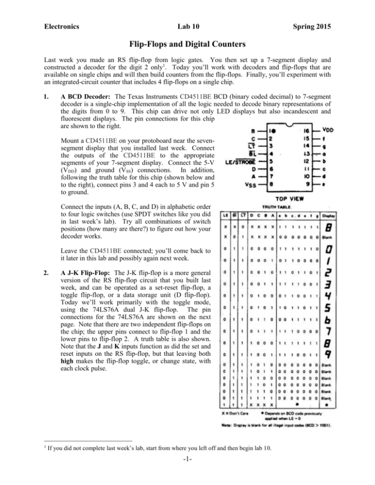
Electronics Lab 10 Spring 2015 Flip-Flops and Digital Counters Last week you made an RS flip-flop from logic gates. You then set up a 7-segment display and constructed a decoder for the digit 2 only1. Today you’ll work with decoders and flip-flops that are available on single chips and will then build counters from the flip-flops. Finally, you’ll experiment with an integrated-circuit counter that includes 4 flip-flops on a single chip. 1. A BCD Decoder: The Texas Instruments CD4511BE BCD (binary coded decimal) to 7-segment decoder is a single-chip implementation of all the logic needed to decode binary representations of the digits from 0 to 9. This chip can drive not only LED displays but also incandescent and fluorescent displays. The pin connections for this chip are shown to the right. Mount a CD4511BE on your protoboard near the sevensegment display that you installed last week. Connect the outputs of the CD4511BE to the appropriate segments of your 7-segment display. Connect the 5-V (VDD) and ground (VSS) connections. In addition, following the truth table for this chip (shown below and to the right), connect pins 3 and 4 each to 5 V and pin 5 to ground. Connect the inputs (A, B, C, and D) in alphabetic order to four logic switches (use SPDT switches like you did in last week’s lab). Try all combinations of switch positions (how many are there?) to figure out how your decoder works. Leave the CD4511BE connected; you’ll come back to it later in this lab and possibly again next week. 2. 1 A J-K Flip-Flop: The J-K flip-flop is a more general version of the RS flip-flop circuit that you built last week, and can be operated as a set-reset flip-flop, a toggle flip-flop, or a data storage unit (D flip-flop). Today we’ll work primarily with the toggle mode, using the 74LS76A dual J-K flip-flop. The pin connections for the 74LS76A are shown on the next page. Note that there are two independent flip-flops on the chip; the upper pins connect to flip-flop 1 and the lower pins to flip-flop 2. A truth table is also shown. Note that the J and K inputs function as did the set and reset inputs on the RS flip-flop, but that leaving both high makes the flip-flop toggle, or change state, with each clock pulse. If you did not complete last week’s lab, start from where you left off and then begin lab 10. -1- Electronics Lab 10 Spring 2015 Mount a 74LS76A. With the power off, connect the 5-V and ground connections to the 74LS76A. In addition, connect pins 2, 3, 4, 7, 8, and 16 to 5 V. Connect the clock of flip-flop 1 (pin 1) to your function generator’s TTL output and also connect the TTL output to an LED (through a suitable resistor) on your protoboard. Connect the flip-flop’s output (1Q) to another logic indicator (LED) of a different color, a few spots to the left of the one you’re using for the TTL. Turn on the power supply and set the FG for a few Hz. Describe the behavior of the two LEDs. Is the flip-flop “toggling;” that is, changing state each time the clock goes low? Now turn the FG up to about 1 kHz. With your oscilloscope, look simultaneously at the FG TTL and the flip-flop output. How do the frequencies of the two signals compare? 3. A 2-Bit Binary Counter: Cascading toggle flip-flops together makes a binary counter. To see this effect, connect the output of flip-flip 1 (i.e., 1Q) in your 74LS76A to the clock input of flip-flop 2 (pin 6). Connect 2Q to an LED (different color would be good!) placed to the left of the one where 1Q is connected. Leave flip-flop 1’s clock connected to the FG TTL and reset the FG to a slow signal of a few Hz. Turn on the power supply and observe the three logic indicators (LEDs) that you now have connected. Verify that the LEDs connected to 1Q and 2Q indicate a binary number that counts the number of clock pulses. (This 2-bit counter only counts modulo-4; that is, it goes from 0 to 3 and then repeats.) Then disconnect the “1” and “2” inputs (i.e., pins 7 and 1) of your CD4511BE from the logic switches and connect them to the appropriate flip-flop outputs. Set the “4” and “8” inputs to 0 using the remaining logic switches. (Why? How many digits are in the number you’re trying to display?) Verify that the 7-segment display gives the same number that appears in binary form on the logic indicators. Finally, look simultaneously at the FG TTL clock and 2Q with your oscilloscope, now using a clock signal at several kHz. How do their frequencies compare? Optional for 104 and 114 and Possible Presentation Topic (talk with me if you’re interested in using this topic for a presentation): What you’ve built is a ripple counter, so called because the count ripples sequentially through the flip-flops. Can you use your JK flip-flops to make a 2-bit synchronous counter whose outputs switch simultaneously? 4. A Decade Counter: You may be able to see how an n-bit counter could be made by cascading n flip-flops. How many states would such a counter have? What would be its maximum count? In -2- Electronics Lab 10 Spring 2015 particular, what would these numbers be for a 4-bit counter? Actually, 4-bit counters are available on a single chip. Some have gating that force a reset to zero before all possibilities are realized; in particular, the 74LS390 is a decade counter, with ten possible states representing the numbers 0 to 9. The pin connections for the 74LS390 are shown to the right. In addition to powering and grounding the chip, connect pin3 with pin 4. 1QA-2QD are the outputs of the eight internal flip-flops. Disconnect your 74LS76A chip from the logic indicators and from the CD4511BE decoder, but leave the 74LS76A on the protoboard with power connected. With the power off, mount a 74LS390 and connect the 5-V supply and ground to pins 16 and 8, respectively. Ground pin 2 and connect pin 3 to pin 4. Connect the FG TTL to the clock input (pin 1). Connect 1QA-1QD to logic indicators, in the appropriate order. Also connect 1QA-1QD to the appropriate inputs of the CD4511BE decoder. Set the FG to provide a slow (several Hz) clock signal, and turn on the power supply. Verify that the counter works, by viewing the output of both the logic indicators and the 7segment display. Now go to a high-frequency clock signal (several kHz), and measure the frequencies of the clock (FG), and the output signals from 1QA, 1QB, 1QC, and 1QD. How do these frequencies compare? Does this result make sense? Explain your thinking. 5. 6. Optional Exercises for 104 and 114 – possible presentation topics: a. Pulse counting: Disconnect the clock input from the FG TTL and connect it instead to a SPDT switch. Verify that the counter counts the number of times you move the switch back and forth. Does the counter advance when the “clock” goes high or low? b. An up/down counter (let me know if you want to attempt this challenge before you begin): Design a circuit that counts from 0 to 9, then automatically reverses and counts back down to 0, then reverses again: 0 1 2 3 4 5 6 7 8 9 8 7 6 5 4 3 2 1 0 1 2 etc. This is not trivial! You will almost certainly need some logic and a flip-flop. It may help to know that the counter changes state when the clock goes high, but the 74LS76A flip-flop changes when it goes low. Wire and verify that it works. Write-up 1. A BCD Decoder Explain how the CD4511BE decoder works and how you figured it out. 2. A J-K Flip-Flop a. Describe the behavior of the two LEDs. b. Is the flip-flop “toggling;” that is, changing state each time the clock goes low? c. How do the frequencies of the FG TTL and the flip-flop output signals compare? Explain. 3. A 2-Bit Binary Counter Using a clock signal of several KHz, how do the frequencies of the FG TTL and the 2Q output signals compare? Explain. 4. A Decade Counter a. How many states would a decade counter have? b. What would be its maximum count? In particular, what would these numbers be for a 4bit counter? Explain. -3- Electronics 5. Lab 10 Spring 2015 c. With a high-frequency clock signal (several kHz), how do the frequencies of the clock (FG), and the output signals from 1QA, 1QB, 1QC, and 1QD compare. Does this result make sense? Explain your thinking. Optional Exercises for 104 and 114 a. Explain how the pulse counting process works. b. Describe your design of an up/down counter. -4-

