Paper
advertisement

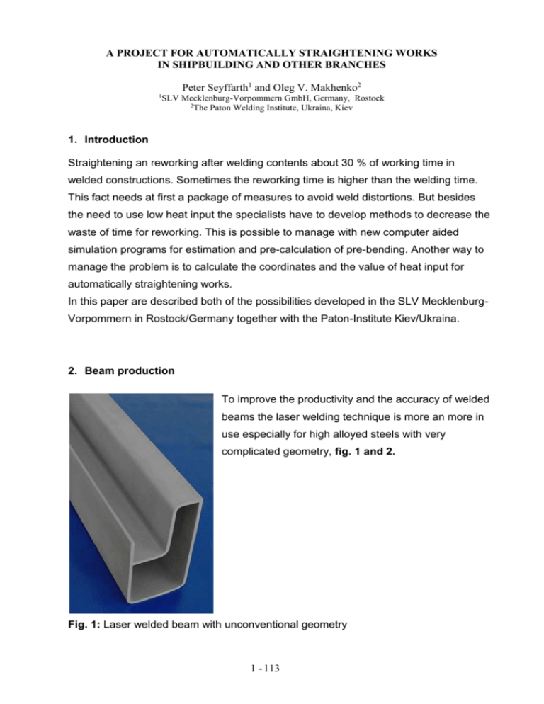
A PROJECT FOR AUTOMATICALLY STRAIGHTENING WORKS IN SHIPBUILDING AND OTHER BRANCHES Peter Seyffarth1 and Oleg V. Makhenko2 1 SLV Mecklenburg-Vorpommern GmbH, Germany, Rostock 2 The Paton Welding Institute, Ukraina, Kiev 1. Introduction Straightening an reworking after welding contents about 30 % of working time in welded constructions. Sometimes the reworking time is higher than the welding time. This fact needs at first a package of measures to avoid weld distortions. But besides the need to use low heat input the specialists have to develop methods to decrease the waste of time for reworking. This is possible to manage with new computer aided simulation programs for estimation and pre-calculation of pre-bending. Another way to manage the problem is to calculate the coordinates and the value of heat input for automatically straightening works. In this paper are described both of the possibilities developed in the SLV MecklenburgVorpommern in Rostock/Germany together with the Paton-Institute Kiev/Ukraina. 2. Beam production To improve the productivity and the accuracy of welded beams the laser welding technique is more an more in use especially for high alloyed steels with very complicated geometry, fig. 1 and 2. Fig. 1: Laser welded beam with unconventional geometry 1 - 113 Fig. 2: Design of laser welded beams The driving forces for this development are the need to use large beams, made of stainless steel, which are not available for structural steelwork. Also the reduced costs achieved by reduced weight, reduced stocks and “Just in Time”-production are driving forces. For the enterprises these facts give an improved competitiveness by improved and more consisted quality. Furthermore the deep narrow welds from one side, the low heat input in the material and following the low thermal distortion, the high production rates and process flexibility are advantages of laser techniques. Also the component design opportunities are enhanced, fig. 3. Fig. 3: Clamping devices for laser welding of beams 1 - 114 At the other hand, there are disadvantages, too. Close fitting and well clamped joints are required, to avoid the so called gap breathening which occurred. Accurate beam alignment is also necessary, because the narrow weld easily miss the joint line if not accurately positioned. Precise beam manipulation equipment is necessary and the total equipment and operation costs are high. Therefore there is a need to calculate by computer simulation the following points: Kinetics of distortion Mechanical forces at clamping Temperature field during welding Residual stresses after welding Prebending and straightening parameters. By the help of the results of computation it is possible to prebend the beams before welding to get after welding and cooling a straight profile, if the equipment design allows prebending. With the same program it is possible, too, to design improved clamping devices The clamps must be very strong and heavy, if the distances between the clamps are very narrow. With increasing distances between the clamps the number of clamps is less and the forces on the clamps are lower. This fact allows to design cheaper clamps with less mass, but the distortion of the welded beam would be higher in this case. Therefore the estimation of the mechanical forces at clamping and the kinetics of distortion is a tool to optimise the clamping design and the accuracy of the beam too. Fig. 4 shows the mask for the data input and fig. 5 gives a snapshot of the kinetics of distortion during welding. Fig. 4: Data input in the program “BEAMS” 1 - 115 The calculation gives very adequate results as it is shown in table 1. Deflection after Welding Calculation Measurement Z-direction 17,63 mm 18,0 mm Y-direction 15,98 mm 16,5 mm Tab. 1: Comparison between calculated and measured distortion of a 6 m beam The final results of the computer simulation program BEAMS are the following: Methods of clamping can be calculated Clamping forces can be calculated Longitudinal shrinkage can be calculated Seam tracking can be delivered Production can be optimised. 3. Sandwich panel production Sandwich panels, fig. 6, have a lot of advantages for ships, bridges, parking houses and Fig. 6: Sandwich-panel for decks and walls in shipbuilding or parking houses so on. The main advantages are shown in fig. 7: 1 - 116 Fig. 7: Advantages of laser welded sandwich panels There is a need to calculate the distortion in case of very large panels because of the very thin upper and lower plate in the sandwich construction and the large range in the construction. This is possible by the help of the computer – aided program “CASSETTA”. Fig. 8 shows the data input mask. Fig. 8: Data input to calculate deformation and prebending for sandwich panels 1 - 117 Fig. 5: Kinetic of distortion of a 4 m long beam at various steps of welding time, calculated by the program BEAMS 1 - 118 4. Project of automatic straightening of plates In a big copper production plant is a need for automatic straightening of catode plates. There are working 60 000 plates to collect copper an their surface by catodic refining. It is a high economical loss, if the plates are deformed and therefore the copper production efficiency is decreasing. A automatically working equipment was proposed to solve the problem of the high number of plates which must be straightening and is now under construction. The basic steps of automatically straightening are the following: Automatically measurement of the deformed surface topography Link and transfer of the surface data to the straightening program Calculation of the numbers, coordinates and the values of heat input Link and transfer of the computed data to heat input machine Fulfilling the operation Finally automatic measurement of evenness and the accuracy of plates. The program based on the simply Gauss distribution of heat around a heat spot and is computed as an one dimensional problem in direction of the radius. The principle of the calculation program is to minimize the deformed plate surface by shrinkage around the heat spots to achieve evenness of the plate. The program allows to estimate the stresses and the strains around the heating spot at every time during heating and cooling depending on the power of heating, on the diameter of heating spot and in connection with this as a function of energy intensity, fig. 9. 1 - 119 Fig. 9: Data input mask The distribution of temperature and of stresses and strains in radius and tangential direction are shown in fig. 10, and the final number and coordinates of heat spots in fig.11 Fig. 10: Calculation of temperature, strains and stresses 1 - 120 Fig. 11: Number and distribution of heating spots for straightening 5. Conclusion There was developed a certain number of computer aides programs to simulate deformation of welded constructions. An effective way to achieve constructions with a high accuracy and in a very short time is the use of automatically straightening process. By the help of this program it needs no more than 10 minutes to straightening a plate with the dimensions 1200 x 1200 x 3,25 made of high alloyed steels from the first measurement up to the last finally measurement to guarantee the evenness of the plate. In this way the use of computer aided simulation programs increases the productivity and efficiency of production processes. 1 - 121


