Enhanced Single-Loop Control Strategies Presentation
advertisement
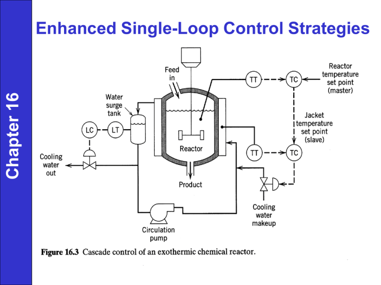
Chapter 16 Enhanced Single-Loop Control Strategies Chapter 16 Chapter 16 Cascade Control (multi-loop) Chapter 16 • Distinguishing features: 1. Two FB controllers but only a single control valve (or other -final control element). 2. Output signal of the "master" controller is the setpoint for “slave" controller. 3. Two FB control loops are "nested" with the "slave" (or "secondary") control loop inside the "master" (or "primary") control loop. • Terminology slave vs. master secondary vs. primary inner vs. outer Chapter 16 Gp1Gd 2 Y1 D2 1 Gc 2GvGp 2Gm 2 Gc1Gc 2GvGp 2Gp1Gm1 (Eq.16-5) Chapter 16 Chapter 16 Chapter 16 Time Delay Compensation • Model-based feedback controller that improves closed-loop performance when time delays are present • Effect of added time delay on PI controller performance for a second order process (t1 = 3, t2 = 5) shown below Chapter 16 Chapter 16 No model error: GC G G*e s G*e s GC 1 GC G* 1 e s GC G*e s GC G Y * Ysp 1 GC G 1 GC G * GC G Y Ysp 1 GC G (16 22) (sensitive to model errors > +/- 20%) Chapter 16 Direct Synthesis Approach (Smith Predictor) Chapter 16 GC GP Y Q( s)e s Ysp 1 GC GP Assume time delay between set-point change and controlled variable (same as process time delay, ). If then G P P(s)es GC C 1 R 1 1 C G P P Pes R Q From Block Diagram, Equating... GC Q GC P(1 Q) 1 1 P P es GC Chapter 16 SELECTIVE CONTROL SYSTEMS (Overrides) For every controlled variable, there must be at least one manipulated variable. Chapter 16 In some applications # of controlled variables •Low selector: •High selector: NC N M # of manipulated variables Chapter 16 Figure 16.13 Control of a reactor hot spot temperature by using a high selector. multiple measurements one controller one final control element Chapter 16 Figure 16.15 A selective control system to handle a sand/water slurry. Override using PI controllers - “old way” (vs. digital logic) 2 measurements, 2 controllers, 1 F.C.E. Chapter 16 Split Range Control 2 Manipulated Vars.: V1 and V2 While V1 opens, V2 should close 1 Controlled Var.: Reactor pressure Chapter 16 3 6 9 15 Chapter 16 Inferential Control Chapter 16 • Problem: Controlled variable cannot be measured or has large sampling period. • Possible solutions: 1. Control a related variable (e.g., temperature instead of composition). 2. Inferential control: Control is based on an estimate of the controlled variable. • The estimate is based on available measurements. – Examples: empirical relation, Kalman filter • Modern term: soft sensor Chapter 16 Gain Scheduling Chapter 16 • Objective: Make the closed-loop system as linear as possible. • Basic Idea: Adjust the controller gain based on current measurements of a “scheduling variable”, e.g., u, y, or some other variable. • Note: Requires knowledge about how the process gain changes with this measured variable. Examples of Gain Scheduling • Example 1. Once through boiler Chapter 16 The open-loop step response are shown in Fig. 16.18 for two different feedwater flow rates. Fig. 16.18 Open-loop responses. • Proposed control strategy: Vary controller setting with w, the fraction of full-scale (100%) flow. Kc wKc , t I t I / w, t D t D / w, • Example 2. Titration curve for a strong acid-strong base neutralization. (16-30) Adaptive Control Chapter 16 • A general control strategy for control problems where the process or operating conditions can change significantly and unpredictably. Example: Catalyst decay, equipment fouling • Many different types of adaptive control strategies have been proposed. • Self-Tuning Control (STC): – A very well-known strategy and probably the most widely used adaptive control strategy. – Basic idea: STC is a model-based approach. As process conditions change, update the model parameters by using least squares estimation and recent u & y data. • Note: For predictable or measurable changes, use gain scheduling instead of adaptive control Reason: Gain scheduling is much easier to implement and less trouble prone. 16-26 Chapter 16 Chapter 16 Figure 16.20 Membership functions for room temperature. Chapter 16 Figure 16.23 Membership functions for the inputs of the PI fuzzy controller (N is negative, P is positive, and Z is zero). Chapter 16 Chapter 16 Chapter 16 Basic Design Information Chapter 16 Final Control System – Distillation Train Chapter 16 Previous chapter Next chapter
