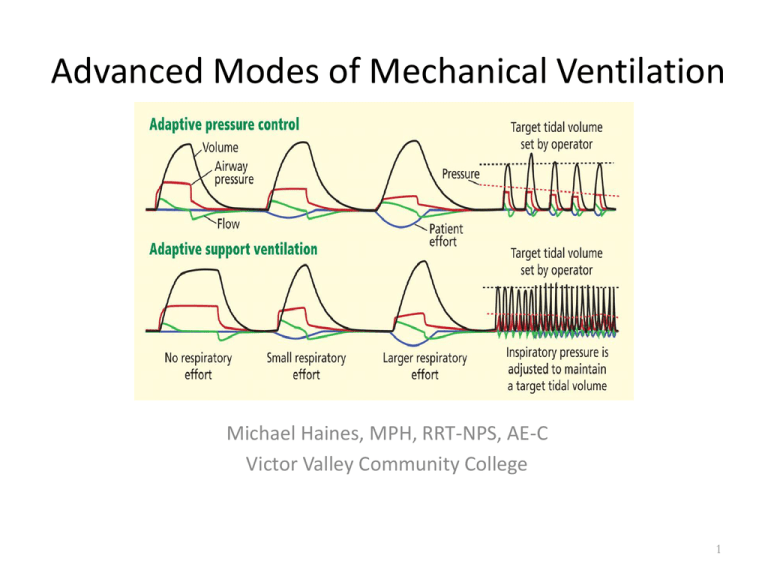
Advanced Modes of Mechanical Ventilation
Michael Haines, MPH, RRT-NPS, AE-C
Victor Valley Community College
1
What we will cover…
–
–
–
–
–
–
–
–
–
–
–
Intro to advanced modes
PRVC
Automode
Volume Support/Variable Pressure
Autoflow
Adaptive Support Ventilation
Volume assured pressure support (VAPS)
Automatic Tube compensation
Mandatory Minute Ventilation
Proportional Assist Ventilation
BUT FIRST A LITTLE REVIEW….
2
• Ventilator Formulas
3
Lung
Mechanics
resistance = Dpressure / Dflow
flow
transairway
pressure
transrespiratory
pressure
volume
transthoracic
pressure
elastance = Dpressure / Dvolume
4
Static Compliance
• Cs = tidal volume corrected for gas compression
Pplat – PEEP total peep
Normal 100 - 200 ml / cmH2O (PDQ)
Decreased with:
•
•
•
•
•
•
•
•
•
•
•
•
Mainstem Intubation
Congestive Heart Failure
ARDS
Atelectasis
Consolidation
Fibrosis
Hyperinflation
Tension Pneumothorax
Pleural Effusion
Abdominal Distension
Chest Wall Edema
Thoracic Deformity
5
Principle #1: Ventilation
The goal of ventilation is to facilitate CO2 release and maintain a normal PaCO2
Minute Ventilation (Ve)
– Total amount of gas exhaled per minute
– Ve = Vt x f
– Ve comprised of 2 factors
VA = alveolar ventilation
VD = dead space ventilation
Ventilation in the ICU setting
– Increased CO2 production
Fever, sepsis, injury, overfeeding
– Increased VD
Vent circuit, ET tube
Adjustments: Vt and f
6
Fig. 13-1. Factors that affect the partial pressure of arterial carbon dioxide
(PaCO2) during mechanical ventilation. V.CO2, carbon dioxide production;
V.A, alveolar ventilation; V.E, minute ventilation; V.D, dead space ventilation; VT,
tidal volume; TI, inspiratory time; TE, expiratory time; f, respiratory rate. (From
Hess DR, MacIntyre NR, Mishoe SC, et al: Respiratory care principles and
7
Principle #2: Oxygenation
The primary goal of oxygenation is to maximize O2 delivery to the blood (PaO2)
Alveolar-arterial O2 gradient
– Equilibrium between O2 in the blood and O2 in the alveoli
– A-a gradient measures efficiency of oxygenation
– PaO2 partially depends on ventilation but more on V/Q
matching
Oxygenation in the ICU setting
– PaO2/PAO2 ratio (a/A ratio)
Indicator of efficiency of O2 transport
– CaO2
Adjustments: FiO2 and PEEP
8
Volume vs. Pressure Control Ventilation
Volume Ventilation
• Volume delivery constant
Pressure Ventilation
• Volume delivery varies
• Inspiratory pressure varies
• Inspiratory pressure constant
• Inspiratory flow constant
• Inspiratory flow varies
• Inspiratory time determined • Inspiratory time set by clinician
by set flow and Vt
9
What’s Wrong with Volume Control
Ventilation?
• The limited flow may not meet the patient’s desired
inspiratory flow rate
• If the patient continues to inspire vigorously -- ,
added, unnecessary work is done
– Can lead to fatigue
• Can cause excessive airway pressure leading to
barotrauma, volutrauma, and adverse hemodynamic
effects
10
Pressure Control Ventilation:
The Alternative
• Definition
– The application of clinician-set inspiratory pressure and inspiratory
time. Flow delivery varies according to patient demand
• The clinician sets the inspiratory pressure, I-time or I:E ratio
and RR
• Tidal volume varies with changes in compliance and
resistance
• Flow delivery is decelerating
11
Pressure Control Ventilation
• May be used in A/C and SIMV modes
• In A/C - all breaths (either machine-initiated
or patient-initiated) are time-cycled and
pressure-limited
• In SIMV - only machine-initiated breaths are
time-cycled and pressure-limited
– Spontaneous breaths can be pressure-supported
12
Pressure Control Ventilation
• Advantages
– Limits risk of barotrauma
– May recruit collapsed and flooded alveoli
– Improved gas distribution
– Uses a active exhalation valve which uses servo-control
technology that allows gas to be released from the exhalation
valve during the inspiratory phase if the patient makes an
expiratory effort.
• Disadvantages
– Tidal volumes vary when patient compliance changes (i.e.,
ARDS, pulmonary edema)
– With increases in I-time, patient may require sedation and/or
chemical paralysis
13
Indications for PCV
• Enhance patient / ventilatory synchrony
– Patient determines flow
• Lung protection strategy
– Lower inspiratory pressure with decelerating flow may
improve V/Q matching
– Adjusting I-time may improve oxygenation
by ↑ MAP
• Alveolar diseases that produce varying time constants
– May recruit alveoli by lengthening I-time
14
Rationale of Pressure Modes
• Ventilator-induced lung injury (VILI)
• Atelectrauma
• Pre-existing lung damage and/or inflammation
15
The Cons of Pressure Control
• Variable Vt as pulmonary mechanics change
• Potentially excessive Vt as compliance
improves
• Inconsistent changes in Vt with changes in PIP
and PEEP
16
Most Commonly used Waveforms
• Pressure vs.
Time
• Flow vs. Time
• Volume vs. Time
17
Pressure-Time Curve
20
Volume Ventilation
Pressure Ventilation
Paw
Expiration
cmH2O
Sec
1
2
3
4
5
6
18
Pressure vs. Time Curve
30
A
B
C
PIP
Baseline
Paw
Mean Airway Pressure
cmH2O
1
2
3
4
Sec
5
6
-10
19
Volume Control Breath Types
60
Paw
SEC
cmH20
-20
120
1
2
3
4
5
6
INSP
SEC
Flow
L/min
1
2
3
4
5
120
6
EXH
If compliance decreases the pressure increases to
maintain the same Vt
20
Volume/Flow Control
Inspiration
Pressure Control
Expiration
20
Inspiration
Expiration
20
Paw
Pressure
Paw
0
1
0
2
20
0
1
2
0
1
2
20
Volume
0
0
1
0
2
3
Flow
0
-3
3
Time (s)
0
-3
Time (s)
21
• These curves illustrate the two basic approaches to ventilator
control. If the ventilator controls flow, it controls volume indirectly
(by definition) and vice versa. Usually, inspiratory flow is held
constant during inspiration, causing volume and pressure to rise
linearly. Inspiration ends (cycles off) when a preset tidal volume is
met.
• In contrast, with pressure control ventilation, airway pressure may
be held constant during inspiration. This causes inspiratory flow to
decay exponentially from its peak value towards zero as volume
rises exponentially. Inspiration usually ends after a preset
inspiratory time or (in the case of pressure support) after a preset
inspiratory flow threshold has been crossed. If inspiratory time is
long enough (usually about 5 time constants) lung pressure will
equilibrate with airway pressure and inspiratory flow will cease.
• You will note that for passive exhalation is exponential. That mean
expiratory time must be at least 5 time constants long to exhale
more that 99% of the tidal volume. As expiratory time becomes
shorter than 5 time constants, gas trapping (ie, autoPEEP) occurs.
22
23
Work to Trigger
30
Paw
cmH2O
Sec
1
2
3
4
5
6
-10
24
Assisted Breath
25
Lung Overdistension
26
Analysis of Compliance Waveforms
Compliance waveforms
simultaneously display
volumes and the amount of
pressure necessary to deliver
these volumes. Volume
normally is plotted on the “Y”
axis and pressure on the “X”
axis.
The curve to the right depicts
a compliance curve from a
patient with normal
compliance and airway
resistance. The arrow pointing
down and to the left is on the
expiratory side of the curve.
27
Analysis of Compliance Waveforms
• One of the clinical
indications for the addition
of positive-end expiratory
pressure (PEEP) is low lung
compliance. If PEEP is
added, the baseline
pressure would then be
elevated and the curve
would shift to the right.
28
Altering Compliance with PEEP
• The curve drawn in a heavy, non-dashed line represents an improved lung
compliance due to the addition of PEEP. Notice that the tidal volume is the
same (note the “Y” axis) while the PIP has fallen (note the “X” axis). Since
the same volume is delivered with less of a pressure difference (PIP-PEEP),
compliance has increased.
29
Compliance Curves
The following series of
compliance curves reflect a
steady fall in lung compliance, as
would occur with the
development of cardiogenic or
noncardiogenic pulmonary
edema. The first curve (1)
reflects the patient’s baseline
condition. As his compliance
falls, higher pressures are
needed to deliver the same tidal
volume (2) (second set of curves
with the initial curve indicated in
gray). As the patient’s condition
deteriorates further, the final
compliance curve is obtained (3).
30
Assist/Control Mechanical Ventilation
Notice that the third
mechanical breath was
preceded by a drop in
airway pressure (indicating
a spontaneous inspiratory
effort). In addition, note
that the TCT had not
elapsed prior to the
initiation of this breath.
Although only one of the
breaths was initiated
spontaneously, all breaths
had the same tidal volume.
31
Synchronized Intermittent Mandatory
Ventilation (SIMV)
Notice that the fifth breath
was a mechanical breath
that was initiated by a
spontaneous inspiratory
effort. If this effort had
occurred before the
sensitivity window began,
the patient would have
only had a spontaneous,
unassisted breath (circled).
In addition, notice that the
therapist selected a
constant flow pattern for
this patient.
32
Support Ventilation (PSV)
• Salient features of the flow graph:
– The amount of inspiratory flow may vary from breath to
breath based on patient inspiratory effort (V1<V2).
– Duration of each breath may vary.
– http://www.youtube.com/watch?v=Rwr5ZjJI1ZQ
33
Support Ventilation (PSV)
• Salient features of the volume graph:
– The tidal volume may vary from breath to breath
based on patient inspiratory effort (V1<V2).
– Duration of each breath may vary.
34
Pressure, Flow, and Volume Curves
A clearer picture of the dynamics
of plateau pressures and
inflation holds is obtained when
pressure curves are viewed along
with their corresponding flow
and volume curves. Notice that
flowrate drops to zero during the
plateau interval, separating
expiratory flow from inspiratory
flow. In addition, even though
flow is not occurring during the
inflation hold, the inflation hold
is still considered to be part of
inspiratory time or Ti. Since no
flow is occurring the volume
does not change during the
pause.
35
Pressure vs. Volume Ventilation
(From Branson, R., Bird product literature)
36
New Modes: Dual Modes
• Within-breath
Adjustment
• Between-Breath
Adjustment
• Automatic Tube
Compensation (ATC)
• Volume Support (VS)
• Volume-Assured
Pressure Support
• Pressure-Regulated
Volume Control
37
Why use newer modes of ventilation?
• Newer ventilators can be set to modes other than the
pressure-control and volume-control modes of older
machines
• The alternative modes of ventilation were developed to
prevent lung injury and asynchrony through patient
adaptation, promote better oxygenation and faster
weaning, and be easier to use.
• However, evidence of their benefit is scant.
• Remember: weaning is a dynamic process requiring
frequent intervention and adjustments, best performed
by the RT!
38
Why use newer modes of ventilation?
• Technologic advances and computerized control
of mechanical ventilators have made it possible
to deliver ventilatory assistance in new modes.
Driving these innovations is the desire to prevent
ventilator induced lung injury, improve patient
comfort, and liberate the patient from
mechanical ventilation as soon as possible
• We call these innovations “alternative” modes to
differentiate them from the plain volume-control
and pressure-control modes
39
•
•
•
•
•
•
•
•
•
•
Terminology
APC—adaptive pressure control
APRV—airway pressure-release
ventilation
ASV—adaptive support ventilation
HFOV—high-frequency oscillatory
ventilation
MMV- Mandatory Minute Ventilation
PAV—proportional assist ventilation
PRVC – Pressure Release Volume
Control
PSV—pressure support ventilation
VC+ - Volume control plus
VS- Volume Support
•
•
•
•
APV- adaptive pressure ventilation
ATC – Automatic tubing
compensation
VP- variable pressure
VTPC- Volume targeted pressure
control
40
Patient-ventilator Asynchrony
• 24% of mechanically ventilated
patients exhibit patient-ventilator
asynchrony in > 10% of their
respiratory efforts during AVC and
PS ventilation
(ineffective triggering and double
triggering).
• Patient-ventilator asynchrony
during assisted mechanical
ventilation
Intensive Care Med. 2006;32:1512
Arnold W. Thille, Pablo Rodriguez, Belen Cabello
Francois Lellouche, Laurent Brochard
Length of Stay
Asynchrony
Sedation
Prolonged
ventilation time1
Possible muscle atrophy2
and VAP3
Weaning is delayed
1. Kollef M et al. Chest. 1998;114:541–548.
2. Levine S et al. NEJM .2008;358:1327-1335.
3. Rello J et al. Chest .2002;122:2115-2121.
Ventilator asynchrony is manifested in
several forms
• Common asynchrony patterns include missed efforts, double triggering
and auto-cycling.
• These problems typically occur when the breath parameters set on the
ventilator do not match the signals from the patient’s respiratory center in
the brain.
• The upper graphic shows multiple missed efforts in the pressure support
mode.
• The lower graphic shows an asynchronous pattern called “double trigger”
in the assist control mode.
• Because patient conditions are constantly changing, frequent
manipulation of the ventilator settings are required to manage the
asynchrony. It is not uncommon for patients to be sedated as a result of
asynchrony and this has been shown to prolong ventilation time.1
Furthermore, prolonged ventilation time can result in rapid disuse atrophy
of the diaphragm2 and ventilator-associated pneumonia.3
Mechanical breath terminology
• Control variable—the mechanical breath goal,
ie, a set pressure or a set volume
• Trigger variable—that which starts inspiration,
ie, the patient (generating changes in pressure
or flow) or a set rate (time between breaths)
• Limit variable—the maximum value during
inspiration
• Cycle variable—that which ends inspiration
44
Mechanical breath terminology
• Continuous mandatory ventilation—all breaths are
controlled by the ventilator, so usually they have the
same characteristics regardless of the trigger (patient
or set rate); no spontaneous breaths are allowed
• Intermittent mandatory ventilation—a set number of
mechanical breaths is delivered regardless of the
trigger (patient initiation or set rate); spontaneous
breaths are allowed between or during mandatory
breaths
• Continuous spontaneous ventilation—all breaths are
spontaneous with or without assistance
45
Mechanical breath terminology
• Set point—the ventilator delivers and maintains a set goal, and this
goal is constant (eg, in pressure control, the set point is pressure,
which will remain constant throughout the breath)
• Servo—the ventilator adjusts its output to a given patient variable
(ie, in proportional assist ventilation,
• the inspiratory flow follows and amplifies the patient’s own flow
pattern)
• Adaptive—the ventilator adjusts a set point to maintain a different
operator-selected set point (ie, in pressure-regulated volume
control, the inspiratory pressure is adjusted breath to breath to
achieve a target tidal volume)
• Optimal—the ventilator uses a mathematical model to calculate the
set points to achieve a goal (ie, in adaptive support ventilation, the
pressure, respiratory rate, and tidal volume are adjusted to achieve
a goal minute ventilation)
46
Examples of the first dual modes
• Volume Assured Pressure Support (VAPS) &
Pressure Augmentation
• Pressure Regulated Volume Control (PRVC) &
similar modes
• Volume Support Ventilation (VS or VSV) &
similar modes
47
NEW MODES OF VENTILATION DUALCONTROLLED MODES
Type
Manufacturer; ventilator
Name
Dual control within a breath
VIASYS Healthcare; Bird
8400Sti and Tbird
VIASYS Healthcare; Bear 1000
Volume-assured pressure
support
Pressure augmentation
Dual control breath to breath:
Pressure-limited flow-cycled
ventilation
Siemens; servo 300
Cardiopulmonary corporation;
Venturi
Volume support
Variable pressure support
Dual control breath to breath:
Pressure-limited time-cycled
ventilation
Siemens; servo 300
Hamilton; Galileo
Drager; Evita4
Pressure-regulated volume
control
Adaptive pressure ventilation
Autoflow
Variable pressure control
Dual control breath to breath:
SIMV
Hamilton; Galileo
Adaptive support ventilation
48
Dual Control Breath-to-Breath
pressure-limited time-cycled ventilation
Pressure Regulated Volume Control
Servo 300
Maquet Servo-i
49
Other Names for PRVC…
AutoFlow (Drager • Medical AG, Lubeck, Germany)
Adaptive Pressure Ventilation (Hamilton
Galileo, Hamilton Medical AG, Bonaduz, Switzerland)
Volume Control+ (Puritan Bennett, Tyco Healthcare;
Mansfield, MA)
Volume Targeted Pressure Control, Pressure
Controlled Volume Guaranteed (Engstrom, General
Electric, Madison, WI).
50
Pressure Regulated Volume Control (PRVC)
• One of the concerns with pressure-control
ventilation is that it cannot guarantee a minimum
minute ventilation in the face of changing lung
mechanics or patient effort, or both.
• To solve this problem, in 1991 the Siemens Servo 300
ventilator introduced Pressure Regulated Volume
Control, a mode that delivers pressure-controlled
breaths with a target tidal volume and that is
otherwise known as adaptive pressure control (APC)
• On the Servo it was initially only available on AC
mode
51
Pressure Regulated Volume Control
(PRVC)
• PRVC is not a volume-control mode (Despite
the name!). In volume control, the tidal
volume does not change; in APC the tidal
volume can increase or decrease, and the
ventilator will adjust the inflation pressure to
achieve the target volume.
• Thus, APC guarantees an average minimum
tidal volume but not a maximum tidal volume
52
Pressure Regulated Volume Control (PRVC)
• Combines volume ventilation & pressure
control
– (for mech., time-cycl. breaths only)
• Set TV is “targeted”
• Ventilator estimates vol./press. relationship
each breath
• Ventilator adjusts level of pressure control
breath by breath
53
Pressure Regulated Volume Control (PRVC)
• Delivers patient or timed triggered, pressuretargeted (controlled) and time-cycled breaths
• Ventilator measures VT delivered with VT set on
the controls. If delivered VT is less or more,
ventilator increases or decreases pressure
delivered until set VT and delivered VT are equal
54
Pressure Regulated Volume Control
(PRVC)
• This mode differs from pressure AC by adjusting rhe
pressure level on a breath-by-breath basis to ensure
a targeted Vt
• The respiratory therapist must set:
–
–
–
–
–
–
–
–
Pressure
Target Vt,
Inspiratory time
Backup rate
Rise time
FiO2
PEEP
Sensitivity
55
Pressure Regulated Volume Control
(PRVC)
• For each breath, the ventilator assesses each
breath and adjusts pressure 1-3 cm H2O and
assesses the Vt
• This mode works best for pts who are apneic
or have a weak ventilatory drive, used on AC
mode and also SIMV (only on Servo I)
56
Pressure Regulated Volume Control (PRVC)
• First breath = 5-10 cm H2O above PEEP
• First breath is a “test breath”, an inspiratory hold
is also applied to obtain a plateau pressure to be
applied on the next breath
• V/P relationship measured
• Next 3 breaths, pressure increased to 75%
needed for set TV
• Then up to +/- 3 cm H2O changes per breath
• Time ends inspiration
57
2nd
1st breath
The pressure is constant after the first test breath (square pattern) and flow
becomes variable with a decelerating ramp pattern just as in pressure control
mode.
58
Pressure Regulated Volume Control (PRVC)
PRVC. (1), Test breath (5 cm H2O); (2) pressure is increased to deliver set volume; (3), maximum
available pressure; (4), breath delivered at preset E, at preset f, and during preset TI; (5), when VT
corresponds to set value, pressure remains constant; (6), if preset volume increases, pressure
decreases; the ventilator continually monitors and adapts to the patient’s needs
59
Press increase +3
The vent then regulates the amount of pressure needed to obtain the
desired set VT. It will increase or decrease the amount of pressure on a
“breath by breath” basis, (+/- 3 cmH2O per breath)
60
PRVC flowchart
Test Breath
Measure tidal
Volume
Decrease
Insp Pressure
More
Compare to
set Tidal
Volume
Less
Increase Insp
Pressure
Equal
Give Same
Insp Pressure
61
Pressure Regulated Volume Control (PRVC)Considerations
• Assist-control mode
• Like PC, flow varies automatically to varying
patient demands
• Constant press. during each breath - variable
press. from breath to breath
• Time is cycling method; delivered TV can vary
from set
62
Pressure Regulated Volume Control (PRVC)Considerations
• The ventilator will not allow delivered
pressure to rise higher than 5 cm H2O
below set upper pressure limit
• Example: If upper pressure limit is set to 35 cm H2O and
the ventilator requires more than 30 cm H2O to deliver a
targeted VT of 500 mL, an alarm will sound alerting the
clinician that too much pressure is being required to deliver
set volume (may be due to bronchospasm, secretions,
changes in CL, etc.)
63
Pressure Regulated Volume Control (PRVC)
• Indications
• Patient who require the lowest possible
pressure and a guaranteed consistent VT
• ALI/ARDS—Questionable, ideally change
to PC, VC with low VT/high rate or APRV
or HFOV
• Patients requiring high and/or variable I
• Patient with the possibility of CL or Raw
changes
64
Pressure Regulated Volume Control (PRVC)
• Disadvantages and Risks
•
•
•
•
•
•
Varying mean airway pressure
May cause or worsen auto-PEEP
When patient demand is increased, pressure level may
diminish when support is needed
May be tolerated poorly in awake non-sedated patients
A sudden increase in respiratory rate and demand may
result in a decrease in ventilator support
Pressure delivered is dependent on VT from previous
breath. If patient intermittently makes a significant
inspiratory effort, it can result in variable volumes that
can be higher or lower than the setting
65
In this example, the first breath is a control breath with the
patient making no respiratory effort this time. The desired
tidal volume of 500 is delivered here.
66
Pressure unchanged
The second breath is triggered by the patient who made a
significant inspiratory effort. Although, PIP has remained the
same as the first breath, a higher tidal volume results because
of higher transpulmonary pressure
67
The ventilator will then reduce the amount of pressure needed
for the next breath. The patient doesn’t make any inspiratory
effort with this breath, the result is a tidal volume that is lower
than the set tidal volume
68
Pressure Regulated Volume Control (PRVC)
• Advantages
•
•
•
•
•
•
Maintains a minimum PIP
Targeted VT and E
Patient has very little WOB requirement
Allows patient control of respiratory rate and
Variable E to meet patient demand
Decelerating flow waveform for improved gas
distribution
• Breath by breath analysis??
E
69
• Understanding PRVC part 1
• Understanding PRVC part 2
70
Auto-mode/Volume Support on PRVC
• For patients that are making intermittent
inspiratory efforts, or breathing spontaneously,
switching to Automode may be better (on Servo,
called adaptive support ventilation on Galelio)
• In Automode, the ventilator will automatically
switch between PRVC and Volume Support mode.
• PRVC breaths when there is no patient effort and
VS breaths with patient effort
71
Auto-mode/Volume Support on PRVC
• Volume Support works the same way as PRVC
• VS automatically adjusts the level of pressure
support needed to achieve a targeted tidal
volume, based on the amount of inspiratory
effort given by the patient
• Volume Support is basically, Pressure Support
that guarantees a set tidal volume
72
VS (Volume Support)
•
•
Entirely a spontaneous mode
Delivers a patient triggered (pressure or flow), pressure
targeted, flow cycled breath
–
•
•
Can also be timed cycled (if TI is extended for some reason) or
pressure cycled (if pressure rises too high).
Similar to pressure support except VS also targets set VT. It
adjusts pressure (up or down) to achieve the set volume
(the maximum pressure change is < 3 cm H2O and ranges
from 0 cm H2O to 5 cm H2O below the high pressure alarm
setting
Used for patients ready to be “weaned” from the ventilator
and for patients who cannot do all the WOB but who are
breathing spontaneously
73
VS (Volume Support)
(1), VS test breath (5 cm H2O); (2), pressure is increased slowly until target volume is achieved; (3),
maximum available pressure is 5 cm H2O below upper pressure limit; (4), VT higher than set VT
delivered results in lower pressure; (5), patient can trigger breath; (6) if apnea alarm is detected,
ventilator switches to PRVC
74
Volume Support (VS)
• Pressure limited
• Flow cycled
• Automatic weaning of pressure support as
long as tidal volume matches the minimum
required to Vt.
75
Volume Support (VS)
• What happens in VS if impedance changes
(higher resistance or less compliance )?
• – TV will decrease, subsequent pressure will be
increased to bring TV back toward the goal.
• Little data to show it actually works.
• • If pressure support level increases to maintain
TV in pt with increased airways resistance, PEEPi
may increase.
• • If minimum TV set too high, weaning may be
delayed
76
VS (Volume Support)
• Advantages
• Guaranteed VT and E
• Pressure supported breaths using the lowest
required pressure
• Decreases the patient’s spontaneous respiratory
rate
• Decreases patient WOB
• Allows patient control of I:E time
• Breath by breath analysis
• Variable I to meet the patient’s demand
77
VS (Volume Support)
• Disadvantages
• Spontaneous ventilation required
• VT selected may be too large or small for
patient
• Varying mean airway pressure
• Auto-PEEP may affect proper functioning
• A sudden increase in respiratory rate and
demand may result in a decrease in
ventilator support
78
Auto Flow-on Drager
Essentially the same as PRVC:
Autoflow is not a specific mode, it can be used with all volume
modes, and is effective during the inspiratory phase.
• Autoflow converts a volume mode to a volume targeted, pressure
limited mode. The goal is to deliver the set tidal at the lowest
possible pressure (plateau pressure) utilizing a decelerating gas flow
pattern.
•Autoflow allows the exhalation valve to behave as a CPAP valve
(threshold resistor) allowing the patient to alter their flow patterns,
enhancing the ability to breathe spontaneously.
•During the inspiratory period the patient is able to exhale, cough
or sigh.
79
Auto Flow-on Drager
• When autoflow is activated, a test breath is delivered at a
pressure of 5 cmH20 above PEEP. The second breath is
delivered at 75% of the set tidal volume. The third breath will
be the set tidal volume, provided the pressure is 3 to 5 cmH20
below the pressure limit.
• The microprocessor algorithm then calculates the minimal
pressure capable of achieving the targeted tidal volume.
Autoflow recalculates compliance with each breath, and the
next breath reflects any change in compliance. As the patients
lung compliance changes, the pressure will adjust up or down
in increments of no more than 3 cmH20 per breath.
80
Adaptive Support Ventilation• Adaptive support ventilation (ASV) evolved as a
form of mandatory minute ventilation
implemented with a daptive pressure control.
• ASV delivers pressure-controlled breaths using
• an adaptive (optimal) scheme “Optimal,” in this
context, means minimizing the mechanical work
of breathing: the machine selects a tidal volume
and frequency that the patient’s brain would
presumably select if the patient were not
connected to a ventilator.
81
Adaptive Support Ventilation- Galileo
vent
A dual control mode that uses pressure
ventilation (both PC and PSV) to maintain a
set minimum Ve (volume target) using the
least required settings for minimal WOB
depending on the patient’s condition and
effort. It automatically adapts to patient
demand by increasing or decreasing support,
depending on the patient’s elastic and resistive
loads
82
Adaptive Support Ventilation- Galileo
vent
• The clinician enters the patient’s IBW, which
allows the ventilator’s algorithm to choose a
required Ve. The ventilator then delivers 100
mL/min/kg. A series of test breaths measures
the system C, resistance and auto-PEEP
• If no spontaneous effort occurs, the ventilator
determines the appropriate respiratory rate,
VT, and pressure limit delivered for the
mandatory breaths
83
Adaptive Support Ventilation- Galileo
vent
• The ventilator initially delivers test breaths, in
which it measures the expiratory time constant
for the respiratory system and then uses this
along with the estimated dead space and normal
minute ventilation to calculate an optimal
breathing frequency in terms of mechanical work.
• The optimal or target tidal volume is calculated as
the normal minute ventilation divided by the
optimal frequency.
84
Adaptive Support Ventilation- Galileo
vent
• I:E ratio and TI of the mandatory breaths are
continually being “optimized” by the ventilator to
prevent auto-PEEP
• If the patient begins having spontaneous breaths,
the number of mandatory breaths decrease and
the ventilator switches to PS at the same pressure
level
• Pressure limits for both mandatory and
spontaneous breaths are always being
automatically adjusted to meet the Ve target
85
ASV: Principle mode of ventilation
Flow E
+
+
Flow I
*
*
no patient activity:
* machine triggered
+ time cycled
patient is active:
* patient triggered
+ flow cycled
Pinsp
PEEP
From Hamilton Medical
86
Adaptive Support Ventilation- Galileo
vent
• The target tidal volume is achieved by the use of APC
This means that the pressure limit is automatically
adjusted to achieve an average delivered tidal
volume equal to the target. The ventilator
continuously monitors the respiratory system
mechanics and adjusts its settings accordingly.
• The ventilator adjusts its breaths to avoid air
trapping by allowing enough time to exhale, to avoid
hypoventilation by delivering tidal volume greater
than the dead space, and to avoid volutrauma by
avoiding large tidal volume
87
: Hamilton Galileo’s
ASV - Considerations
• Mandatory breaths = PC, pt. triggered = PS
– both at same targeted TV and calculated press.
• If pt.’s f > “set” by vent., mode is PS
• If pt.’s f < “set” by vent., mode is PC-SIMV/PS
• If patient is apneic, all breaths are PC
88
Ventilator settings
in adaptive support ventilation
•
•
•
•
•
Ventilator settings in ASV are:
Patient height (to calculate • the IBW), Sex
Percent of normal predicted minute ventilation goal
Fio2
PEEP
• Clinical applications of adaptive support
ventilation
• ASV is intended as a sole mode of ventilation,
• from initial support to weaning.
89
Theoretical benefits of adaptive
support ventilation
• In theory, ASV offers automatic selection of
ventilator settings, automatic adaptation to
changing patient lung mechanics, less need for
human manipulation of the machine, improved
synchrony, and automatic weaning
• Physiologic benefits. Ventilator settings are
adjusted automatically. ASV selects different tidal
volume-respiratory rate combinations based on
respiratory mechanics in passive and paralyzed
patients
90
Clinical Evidence for ASV
• In actively breathing patients, there was no difference in
the ventilator settings chosen by ASV for different clinical
scenarios (and lung physiology).10 Compared with
pressure-controlled intermittent mandatory ventilation,
with ASV, the inspiratory load is less and patientventilator interaction is better
• Two trials suggest that ASV may decrease time on
mechanical ventilation. However, in another trial,16
compared with a standard protocol, ASV led to fewer
ventilator adjustments but achieved similar postsurgical
weaning outcomes.
91
92
Disadvantages ASV
• Inability to recognize and adjust to changes in
alveolar VD
• Possible respiratory muscle atrophy
• Varying mean airway pressure
• In patients with COPD, a longer TE may be
required
• A sudden increase in respiratory rate and
demand may result in a decrease in ventilator
support
93
Clinical Evidence for ASV
•
•
•
•
•
•
•
•
•
Adaptive support ventilation: Bottom line
ASV is the first commercially available mode
that automatically selects all the ventilator
settings except PEEP and Fio2. These seem
appropriate for different clinical scenarios
in patients with poor respiratory effort or in
paralyzed patients. Evidence of the effect in
actively breathing patients and on outcomes
such as length of stay or death is still lacking
94
• Initializing ASV
• ASV in Obese patient
95
Volume Assured Pressure Support
(VAPS)
• Designed to reduce work of breathing while
maintaining a minimum minute volume and a
minimum Vt
• Combines a high initial flow as in PC and a
constant volume delivery as in VC
• This mode allows a feedback loop based on tidal
volume
• Switches even within a single breath from
pressure control to volume control if minimum
tidal volume has not been achieved
96
Volume Assured Pressure Support
(VAPS)
• The respiratory therapist sets:
–
–
–
–
–
–
–
–
Pressure limit = plateau seen during VC
RR
Peak flow rate
PEEP
FiO2
Trigger sensitivity
Minimum tidal volume
Also called AVAPS used in NPPV on Respironics Bipap
97
Pressure limit
overridden
40
Set pressure limit
Paw
cmH20
-20
0.6
Volume
L
Set tidal volume cycle threshold
Tidal volume
Tidal volume
not met
met
0
60
Inspiratory flow
greater than set flow
Flow cycle
Set flow limit
Inspiratory flow
equals set flow
Flow
L/min
60
Switch from Pressure control to
Volume/flow control
98
Volume Assured Pressure Support
(VAPS) Limitations
• If pressure too high, all breaths are pressure
limited
• If peak flow is set too low, the switch from
pressure to volume is late in the breath,
inspiratory time is too long.
• Once a breath is triggered, rapid, variable flow
pushes pressure to reach set pressure support
level.
• Tidal volume delivered from the machine is
monitored.
99
Volume Assured Pressure Support (VAPS)
•
Combines volume ventilation & pressure support
– (for mech., vol. limited breaths only)
•
•
•
Uses TV, peak flow, and pressure sup./control settings
Targets PS level with at least set peak flow first
Continues until flow decreases to set peak flow, then:
– If TV not delivered, peak flow maintained
until vol. limit
– If TV or more delivered, breath ends
100
VAPS: Volume Assured Pressure
Support
(From Branson, R., Bird product literature)
101
VAPS: (and Pressure Augmentation) Considerations
• The set TV is the minimum TV the patient will
receive
• The set pressure support is the minimum the
patient will receive
• The set peak flow is the minimum the patient
will receive
• No ventilatory mechanics measured
102
VAPS vs. VS
• How does volume support differ from
• VAPS ?
– In volume support, we are trying to adjust
pressure so that, within a few breaths, desired
TV is reached.
– In VAPS, we are aiming for desired TV tacked
on to the end of a breath if a pressure-limited
breath is going to fail to achieve TV
103
Automatic Tube Compensation (ATC)
• Additional Work of Breathing
– Tube resistance causes the highest workload for
patients with normal lung mechanics
– Tube resistance is proportional to the flow
– Tube resistance increases with smaller tubes
–
New Modes of Ventilatory Support in Spontaneously Breathing Intubated Patients by Stocker et al,
Yearbook of Intensive Care and Emergency Medicine 1997: 514-533
104
Automatic Tube Compensation (ATC)
• How Does It Work?
– The spontaneously breathing intubated patient has to perform
work of breathing to overcome the tube resistance
– ATC takes over the work of breathing induced by the tube
resistance
– The patient breathes like without any tube
–
Respiratory comfort of automatic tube compensation and inspiratory pressure support in conscious humans by
Guttman, J. et al, Intensive Care Medicine 1997, Vol. 23, No. 11, 1119-1124
105
Automatic Tube Compensation (ATC)
• Benefits
– Patient comfort
• ATC adjusts on-line the pressure to compensate the
pressure drop over the tube caused by the current
inhaled gas flow of the patient
– Stocker et al have suggested that a patient’s
breathing during ATC looks like it would if the
patient was extubated – “electronic extubation”
• Cannot predict airway patency, after extubation
106
With ATC switched ON, if patient inhales with a higher flow rate, Evita increases the
support pressure within the breath and vice versa. The pressure is automatically
adjusted in real time about 200 times within an inspiration. Thus ATC compensates for
the resistive work load of the endotracheal tube. Patient experiences "Virtual
Extubation".
107
MMV (Mandatory Minute
Ventilation)
•
•
•
AKA: Minimum Minute Ventilation or Augmented
minute ventilation
Operator sets a minimum E which usually is 70% 90% of patient’s current E. The ventilator
provides whatever part of the E that the patient
is unable to accomplish. This accomplished by
increasing the breath rate or the preset pressure.
It is a form of PSV where the PS level is not set,
but rather variable according to the patient’s need
108
MMV (Mandatory Minute Ventilation)
• Indications
– Any patient who is spontaneously and is
deemed ready to wean
– Patients with unstable ventilatory drive
• Advantages
– Full to partial ventilatory support
– Allows spontaneous ventilation with safety
net
– Patient’s E remains stable
– Prevents hypoventilation
109
MMV (Mandatory Minute Ventilation)
• Disadvantages
• An adequate E may not equal sufficient A (e.g.,
rapid shallow breathing)
• The high rate alarm must be set low enough to
alert clinician of rapid shallow breathing
• Variable mean airway pressure
• An inadequate set E (>spontaneous E) can
lead to inadequate support and patient fatigue
• An excessive set E (>spontaneous E) with no
spontaneous breathing can lead to total support
110
PAV (Proportional Assist Ventilation)
• Patients who have normal respiratory drive but who have
difficulty sustaining adequate spontaneous ventilation are
often subjected to pressure support ventilation (PSV), in
which the ventilator generates a constant pressure
throughout inspiration regardless of the intensity of the
patient’s effort.
• In 1992, Younes and colleagues19,20 developed proportional
assist ventilation (PAV) as an alternative in which the
ventilator generates pressure in proportion to the patient’s
effort. PAV became commercially available in Europe in 1999
and was approved in the United States in 2006, available on
the Puritan Bennett 840 ventilator
111
PAV (Proportional Assist Ventilation)
• Provides pressure, flow assist, and
volume assist in proportion to the
patient’s spontaneous effort, the greater
the patient’s effort, the higher the flow,
volume, and pressure
• The operator sets the ventilator’s volume and
flow assist at approximately 80% of patient’s
elastance and resistance. The ventilator then
generates proportional flow and volume assist to
augment the patient’s own effort
112
Ventilator settings
in proportional assist ventilation
•
•
•
•
•
•
•
•
Ventilator settings in PAV are:
Airway type (endotracheal tube, tracheostomy)
Airway size (inner diameter)
Percentage of work supported (assist range 5%–95%)
Tidal volume limit
Pressure limit
Expiratory sensitivity (normally, as inspiration
ends, flow should stop; this parameter tells the
ventilator at what flow to end inspiration).
113
PAV (Proportional Assist Ventilation)
• Indications
• Patients who have WOB problems
associated with worsening lung
characteristics
• Asynchronous patients who are stable
and have an inspiratory effort
• Ventilator-dependent patients with COPD
115
How does the clinician know where to set the
“%Support”?
Sound clinical
assessment
Work of Breathing
(WOB) bar
The PB 840 has the option of measuring WOB
Sound Clinical Assessment.
• Vital signs
• ABG
• Signs of respiratory distress
– Respiratory rate > 40
breaths/minute PLUS…
– Marked use of
accessory muscles
– Diaphoresis
– Abdominal paradox
– Marked complaint of
dyspnea
– Etc…
PAV (Proportional Assist Ventilation)
• Advantages
– The patient controls the ventilatory variables ( I, PIP,
TI, TE, VT)
– Trends the changes of ventilatory effort over time
– When used with CPAP, inspiratory muscle work is
near that of a normal subject and may decrease or
prevent muscle atrophy
– Lowers airway pressure
118
Ventilatory Demand
The practitioner’s typical response to an increase in demand is what?
Or
Sedate
Increase Support
These can lead to disuse atrophy of the respiratory
muscles or lowering of the CO2 set point.
PAV™+ Software Option Clinical Description
Management tips from Dr. Magdy Younes, inventor
• Start patients at 70% and wean back to stabilize
• When disease process has sufficiently reversed,
decrease %Support over 2 hr intervals
• On average, patients will breathe at 7 mL/kg; some
may want less while others may want more
• Some patients have a high rate normally, so a high rate
on PAV+ may or may not reflect distress; check other
signs; try increasing assist to see if rate goes down
• Don’t be surprised if respiratory rate climbs when
switching from other modes
Dr. Younes is the inventor of Proportional Assist/PAV. The tips in this presentation are
his suggestions and are not necessarily those of Tyco Healthcare/Puritan Bennett.
Proportional Assist and PAV are trademarks of The University of Manitoba and are used
under license by Puritan Bennett.
PAV (Proportional Assist Ventilation)
•
Disadvantages
–
–
–
–
–
Patient must have an adequate spontaneous respiratory drive
Variable VT and/or PIP
Correct determination of CL and Raw is essential (difficult).
Both under and over estimates of CL and Raw during ventilator
setup may significantly impair proper patient-ventilator
interaction, which may cause excessive assist (“Runaway”) – the
pressure output from the ventilator can exceed the pressure
needed to overcome the system impedance (CL and Raw)
Air leak could cause excessive assist or automatic cycling
Trigger effort may increase with auto-PEEP
121
PAV+ is NOT recommended for…
Low drive
due to
meds.
Abnormal
breathing
pattern.
Extreme air
trapping.
Large
mechanical
leaks (TEF).
122
PSV
PAV
Paw
Flow
V
T
PD
I
0.2 sec/div
Review
What is it, why do we use it, what do we set and who
does it benefit?
-APRV
-PRVC
-Autoflow
-Volume support
-Adaptive Support Ventilation
-Volume Assured Pressure Support
-MMV
-PAV
-ATC
124

