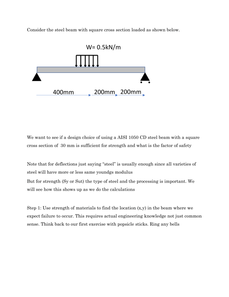
Consider the steel beam with square cross section loaded as shown below. W= 0.5kN/m 400mm 200mm 200mm We want to see if a design choice of using a AISI 1050 CD steel beam with a square cross section of 30 mm is sufficient for strength and what is the factor of safety Note that for deflections just saying “steel” is usually enough since all varieties of steel will have more or less same youndgs modulus But for strength (Sy or Sut) the type of steel and the processing is important. We will see how this shows up as we do the calculations Step 1: Use strength of materials to find the location (x,y) in the beam where we expect failure to occur. This requires actual engineering knowledge not just common sense. Think back to our first exercise with popsicle sticks. Ring any bells Step 2: usually we can do this by looking at places where (a) bending moment is high (b) torque is high (c) shear force is high (d) compression is high (buckling) In our case we use (a) write singularity functions and draw SFD and BMD (excel helps here) Step 2: now find the location of maximum bending moment. It is also the place where shear force is zero . Why? Step 3: find the bending moment at the critical location Step 4: find the stress due to bending moment: y P x Stress components due to each effect 5: Upto now it is all mechanics, now we come to the materials part. Now look at material properties: AISI 1040 CD (Sy 490 MPA) % elongation at failure 12% Step 6: decision chart: Step 7: combine stresses, apply the appropriate failure criterion (computing principal stresses if required) NOTE: you can only add stress components if they are at the same location (x,y) AND if they have the same subscripts (PLANE and NORMAL) You cannot add normal stresses if they act at different points or on different planes You cannot add shear stresses if they act at different points, or act on different planes or if they are in different directions (different subscripts)


