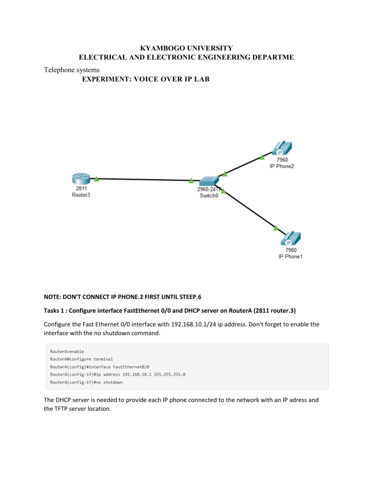
KYAMBOGO UNIVERSITY ELECTRICAL AND ELECTRONIC ENGINEERING DEPARTME Telephone systems EXPERIMENT: VOICE OVER IP LAB NOTE: DON’T CONNECT IP PHONE.2 FIRST UNTIL STEEP.6 Tasks 1 : Configure interface FastEthernet 0/0 and DHCP server on RouterA (2811 router.3) Configure the Fast Ethernet 0/0 interface with 192.168.10.1/24 ip address. Don't forget to enable the interface with the no shutdown command. The DHCP server is needed to provide each IP phone connected to the network with an IP adress and the TFTP server location. After configuring the ISR router, wait a moment and check that ‘IP Phone 1’ has received an IP address by placing your cursor over the phone until a configuration summary appears. Tasks 2 : Configure the Call Manager Express telephony service on Router 3 You must now configure the Call Manager Express(CME) telephony service on Router3 to enable voip on your network. Task 4 : Configure a voice vlan on Switch 3 Apply the following configuration on Switch interfaces. This configuration will separate voice and data traffic in different vlans on Switch . data packets will be carried on the access vlan. Task 5 : Configure the phone directory for IP Phone 1 Although ‘IP Phone 1’ is already connected to Switch, it needs additional configuration before being able to communicate. You need to configure Router CME to assign a phone number to this IP phone. Verify the configuration Ensure that the IP Phone receives an IP Address and a the phone number 54001 from RouterA (this can take a short while). Task 6 : Configure the phone directory for IP Phone 2 Connect IP Phone 2 to Switch A and power the phone ON using the power adapter (Physical tab). Task 7 : Verify the configuration Ensure that the IP Phone 2 receives an IP Address and a the phone number 54002 from Router (this can take a short while). Same procedure as task n°5. Dial 54001 and check if IP phone 1 correctly receives the call.
