Technical Datasheet TRANSFORMER RECTIFIER
advertisement
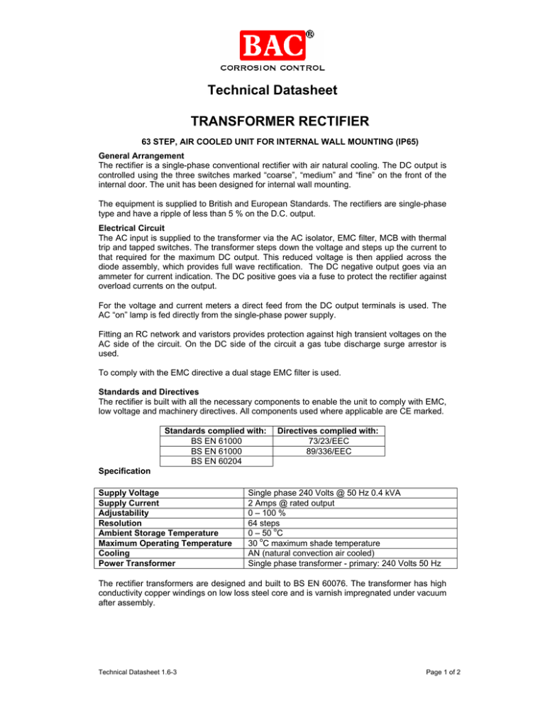
Technical Datasheet TRANSFORMER RECTIFIER 63 STEP, AIR COOLED UNIT FOR INTERNAL WALL MOUNTING (IP65) General Arrangement The rectifier is a single-phase conventional rectifier with air natural cooling. The DC output is controlled using the three switches marked “coarse”, “medium” and “fine” on the front of the internal door. The unit has been designed for internal wall mounting. The equipment is supplied to British and European Standards. The rectifiers are single-phase type and have a ripple of less than 5 % on the D.C. output. Electrical Circuit The AC input is supplied to the transformer via the AC isolator, EMC filter, MCB with thermal trip and tapped switches. The transformer steps down the voltage and steps up the current to that required for the maximum DC output. This reduced voltage is then applied across the diode assembly, which provides full wave rectification. The DC negative output goes via an ammeter for current indication. The DC positive goes via a fuse to protect the rectifier against overload currents on the output. For the voltage and current meters a direct feed from the DC output terminals is used. The AC “on” lamp is fed directly from the single-phase power supply. Fitting an RC network and varistors provides protection against high transient voltages on the AC side of the circuit. On the DC side of the circuit a gas tube discharge surge arrestor is used. To comply with the EMC directive a dual stage EMC filter is used. Standards and Directives The rectifier is built with all the necessary components to enable the unit to comply with EMC, low voltage and machinery directives. All components used where applicable are CE marked. Standards complied with: BS EN 61000 BS EN 61000 BS EN 60204 Directives complied with: 73/23/EEC 89/336/EEC Specification Supply Voltage Supply Current Adjustability Resolution Ambient Storage Temperature Maximum Operating Temperature Cooling Power Transformer Single phase 240 Volts @ 50 Hz 0.4 kVA 2 Amps @ rated output 0 – 100 % 64 steps 0 – 50 oC 30 oC maximum shade temperature AN (natural convection air cooled) Single phase transformer - primary: 240 Volts 50 Hz The rectifier transformers are designed and built to BS EN 60076. The transformer has high conductivity copper windings on low loss steel core and is varnish impregnated under vacuum after assembly. Technical Datasheet 1.6-3 Page 1 of 2 Technical Datasheet Enclosure Type Material Ingress Finish Outdoor, wall mounting, non-hazardous area Manufactured from 2 mm mild steel The Enclosure is IP65 rated Grey to RAL 7032 DC Ripple Less than 5 % from 1 % to 100 % of DC output Protection The equipment is provided with the following devices for protection against over voltage and over current conditions. 1. Primary: 1 x 2 pole magnetic and thermal trip 2. Secondary: 2 x semi-conductor fuse in AC line to diode assembly 3. DC Output: 1 x fuse 4. Control Circuit: 1 x anti-surge fuse. 5. Transient over voltage surge suppression on AC and DC sides of rectifier: 2 x anti surge voltmeter fuses Cable Entry The unit is fitted with a gland plate located at the bottom of the enclosure. Cable access should come from the bottom of the unit. Meters The equipment is fitted with a DC voltmeter and ammeter (DIN 72 type, moving coil to IEC 51, BS89 class 1.5). Control To control the DC output three switches marked “coarse”, “medium” and “fine” are fitted to the internal door of the unit and can be adjusted by manual operation. Each switch has four positions giving a maximum of 1.6 % (63 in number) steps. Accessories The equipment is supplied complete with the following: • Rating plate • Operation and maintenance manual with circuit and outline drawings • Test and inspection reports • Certificate of conformity. Tests • • • • • • Insulation resistance test No load tests Load tests conducted DC output voltage and current. Full load input watts and current Efficiency Function tests Optional Extras The following items can be supplied as optional extras: • In built current interrupter • Remote monitoring by 4-20 mA converters for connection to SCADA systems or SMS Technical Datasheet 1.6-3 Page 2 of 2


