note 9.
advertisement
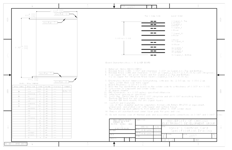
4 3 6.299 DWG.NO. SH 2857 D A +.000 -.012 note 9. +.000 .100-.012 1 REV. Top - Comp.Side Layer Order D 1.Signal_1, Top 2.Ground note 7. 3.Signal_2 4.Power 5.Signal_3 6.Power 7.Signal_10 8.Power 0.095 +/- 0.008 2.550 -.012 +.000 9.Power 10.Signal_11 11.Power +.000 9.187-.012 12.Signal_7 13.Ground 14.Signal_8 15.Ground C C 16.Signal_6, Bottom Board Characteristics - 16 LAYER BOARD 1. Material: Nelco N4000-13EPSI 2. Minimum trace width: 0.006" and clearence: 0.005" on Signal_1,6 (Top and Bottom); 3. Minimum trace width and clearence: 0.005" on Signal_2,3,4,5,7,8,9,10,11,12 (all stripline); note 7. 4. 1 oz copper for 1/2 oz copper for Stripline trace layers (Signal_2,3,4,5,7,10,11,12). +.000 .100-.012 BOARD's all power layers and for Signal_1,2 (Top and Bottom) 5. Electroless Nickel Immersion Gold plating, with min. Ni: 2.5-5 um; Au: 0.05-0.2 um. note 9. DRILL SCHEDULE Apply Solder Mask over bare copper. 6. Board Thickness: 0.093 +/- 0.008 DRILL SYMBOL B DRILL SIZE COUNT PLATED Tolerance 7. Mill the Top and Bottom of board on the solder side to a thickness of 0.063" +/- 0.008 COMMENT 8. Silkscreen on Component and Solder Sides. .009 1124 YES --- .0091 1651 YES --- .011811024 22 YES --- .02 2 YES --- 12. Zc=55 Ohm, Zd=100 Ohm for all 0.005" stripline and all 0.006" microstrip traces. .033464567 2 YES --- Perform TDR test for all signal layers. .035 40 YES --- Present TDR test results for all signal layers. .037401575 18 YES --- 13. Via Fill and Overplate: .041 562 YES --- .041338583 20 YES --- .042 20 YES --- .057 2 YES --- .059 6 YES --- .061023622 4 YES --- .066 22 YES --- .067 24 YES --- .07 4 YES --- 9. 45 degree chamfer. Note 13 11. Interlayer spacing as specified. Vias of this diameter must be completely filled with Peters PP-2795 or equivalent, planarized, and plated over with Copper and surface finish. The plated cap must adhere to fill material after 1x 550F solder shock. 14. Remove all non-functional inner layer pads for pins and vias. 15. Do not increas size of thermal pads and associated spoke connections on 0.041" and 0.0413" holes. UNLESS OTHERWISE SPECIFIED .091 13 YES 6 NO --- .12598425 2 NO --- .12795276 7 YES --- .15 4 NO --- UNIVERSITY OF CHICAGO TOLERANCES ARE: DECIMALS ELECTRONICS DEVELOPMENT GROUP ANGLES .XX APPROVALS .XXX --- .106 CONTRACT NO. DIMENSIONS ARE IN INCHES FRACTIONS A DATE DRAWN M.Bogdan 9/30/2015 CHECKED M.Bogdan 9/30/2015 TREATMENT FINISH SIMILAR TO ACT.WT Annie's Central Card Specification Drawing SIZE SCALE 4 3 FSCM NO. 2 DWG.NO. REV. 2857 B CALC WT A TITLE DO NOT SCALE DRAWING ISSUED THIS SHEET IS COMPUTER GENERATED B 10. FHS tolerances: +/- 0.003 unless specified otherwise. 1/2 A SHEET 1
