D C 4 1
advertisement
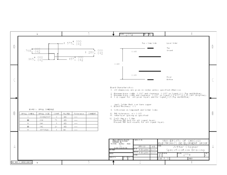
4 3 DWG.NO. SH 2774 +.000 1.575-.012 D A Top - Comp.Side Layer Order D Top +.000 .768-.012 .965 1 REV. 1.280 +.000 Ground 0.005 -.012 +.000 .157-.012 +.000 -.012 0.063 -.012 +.000 2.550 0.005 Power C C Bottom Board Characteristics 0. All dimensions are given in inches unless specified otherwise. 2. Minimum trace width: 0.006" and clearence: 0.005" on Signal_1,6 (Top and Bottom); 3. Minimum trace width and clearence: 0.005" on Signal_2,3,4,5,7,8,9,10 (all stripline); 4. 1 oz copper for all power layers and for Signal_1,2 (Top and Bottom) Apply Solder Mask over bare copper. 6. Board Thickness: 0.0 . B BOARD's DRILL SYMBOL DRILL SCHEDULE DRILL SIZE 8. Silkscreen on Component and Solder Sides. COUNT PLATED Tolerance COMMENT B 10. FHS tolerances: +/- 0.003 11. Interlayer spacing as specified .0098425197 . 9 YES .--- 12. Zc=50 Ohm +/- 5 Ohm .014 . 75 YES .--- .041 . 3 YES .--- .042 . 20 YES .--- .13779528 . NO .--- 1 . Perform TDR test for all signal layers. . Present TDR test results for all signal layers. UNLESS OTHERWISE SPECIFIED CONTRACT NO. UNIVERSITY OF CHICAGO DIMENSIONS ARE IN INCHES TOLERANCES ARE: FRACTIONS DECIMALS ELECTRONICS DEVELOPMENT GROUP ANGLES .XX A APPROVALS .XXX DATE TITLE DRAWN M.Bogdan 12/8/11 CHECKED M.Bogdan 12/8/11 FINISH SIMILAR TO ACT.WT Specification Drawing SIZE CALC WT SCALE THIS SHEET IS COMPUTER GENERATED 4 3 FSCM NO. 2 DWG.NO. REV. 2774 B ISSUED A Jitter Cleaner DO NOT SCALE DRAWING TREATMENT 1/1 A SHEET 1
