LED Polarity Tester
advertisement

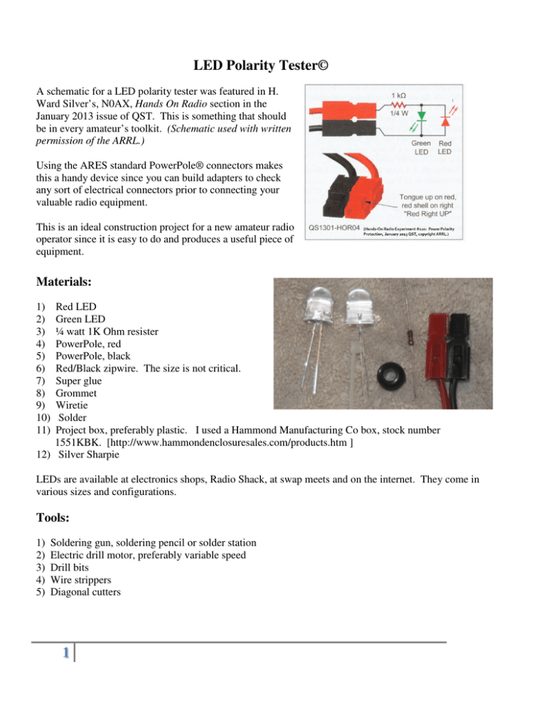
LED Polarity Tester© A schematic for a LED polarity tester was featured in H. Ward Silver’s, N0AX, Hands On Radio section in the January 2013 issue of QST. This is something that should be in every amateur’s toolkit. (Schematic used with written permission of the ARRL.) Using the ARES standard PowerPole® connectors makes this a handy device since you can build adapters to check any sort of electrical connectors prior to connecting your valuable radio equipment. This is an ideal construction project for a new amateur radio operator since it is easy to do and produces a useful piece of equipment. Materials: 1) 2) 3) 4) 5) 6) 7) 8) 9) 10) 11) Red LED Green LED ¼ watt 1K Ohm resister PowerPole, red PowerPole, black Red/Black zipwire. The size is not critical. Super glue Grommet Wiretie Solder Project box, preferably plastic. I used a Hammond Manufacturing Co box, stock number 1551KBK. [http://www.hammondenclosuresales.com/products.htm ] 12) Silver Sharpie LEDs are available at electronics shops, Radio Shack, at swap meets and on the internet. They come in various sizes and configurations. Tools: 1) 2) 3) 4) 5) Soldering gun, soldering pencil or solder station Electric drill motor, preferably variable speed Drill bits Wire strippers Diagonal cutters 1 Construction 1) Examine the LEDs and note that one lead is longer than the other. This is the anode or positive side. The other lead is the cathode or negative side. Some LEDs have a flat spot on the cathode side for identification. 2) Mark the green LED on the underside with a sharpie. This will keep you from confusing them later. 3) Lay out the drill pattern on the plastic enclosure. 4) Drill holes for the LEDs. If you are using large LEDs you may wish to drill a pilot hole first. Drill at a very slow speed - plastic tends to bind drill bits at high speed and the bit can grab the enclosure and damage it. 5) Remove any burrs from the holes. 6) Drill an appropriate sized hole in the end of the enclosure for the grommet and zipwire. 7) Press the LEDs into the holes from the inside of the box. The green LED long lead (+) should be on the same side of the box as the red LED short lead (-). 2 8) Twist the LED leads together and double check The time to get it all laid out properly is before you polarity. solder! 9) Feed the red/black zipcord through the grommet into the box. Separate the red side from the black side and strip the end of the wire. Twist the conductor strands to hold them together. Note that I have marked the polarity with a Silver Sharpie. If you don’t have a Silver Sharpie in your kit, I suggest that you pick one up on your next trip to Office Depot. They are ideal for marking electronic components, wall wart transformers, etc. 10) Solder the dropping resistor to the end of the wire. Resistors are not polarized, so it does not matter which end you use. The resister is necessary to reduce the input voltage. 11) Solder the other end of the resistor to the green LED +/red LED – leads. 12) Strip the end of the black wire and solder it to the green LED -/red LED+ leads. Solder contains lead, so when you are done, wash your hands thoroughly! 3 13) Put a drop or two of super clue on the diodes on the inside of the box to secure them. 14) Bend the leads so they will fit inside the case with the lid on. Make sure the leads do not touch each other. 15) Pull the cable to snug the leads down. Install a small wiretie to secure it. 16) Attach the box lid. 17) Install PowerPole connectors on the other end of the zip cable. 18) You are done! Test it out! 4 Construction notes for the tool impaired or those that do not have ready access to supplies. As long as you stick to the schematic you have a lot of options. • • • • Use a film canister, PVC cap, Altoids tin or pill bottle for the project box. Use salvage zip cord that is not color coded, but be careful with polarity Clear fingernail polish will secure the LEDs on most surfaces if you don’t have super glue handy If you do not have wire cutters and strippers, use a pair of fingernail clippers Copyright 2013. Lynn Burlingame 5

