transducer V 77
Input
Measurement
Most IMP Questions on Unit V: Transducers
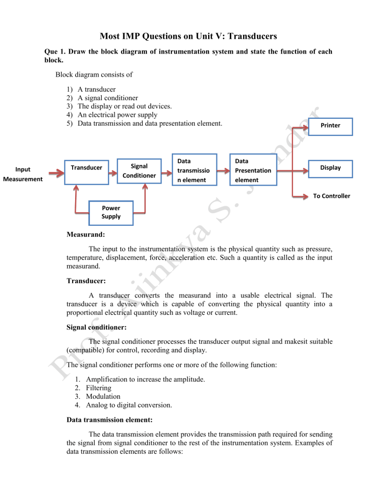
Que 1. Draw the block diagram of instrumentation system and state the function of each block.
Block diagram consists of
1) A transducer
2) A signal conditioner
3) The display or read out devices.
4) An electrical power supply
5) Data transmission and data presentation element.
Printer
Transducer
Power
Supply
Signal
Conditioner
Data transmissio n element
Data
Presentation element
Display
To Controller
Measurand:
The input to the instrumentation system is the physical quantity such as pressure, temperature, displacement, force, acceleration etc. Such a quantity is called as the input measurand.
Transducer:
A transducer converts the measurand into a usable electrical signal. The transducer is a device which is capable of converting the physical quantity into a proportional electrical quantity such as voltage or current.
Signal conditioner:
The signal conditioner processes the transducer output signal and makesit suitable
(compatible) for control, recording and display.
The signal conditioner performs one or more of the following function:
1.
Amplification to increase the amplitude.
2.
Filtering
3.
Modulation
4.
Analog to digital conversion.
Data transmission element:
The data transmission element provides the transmission path required for sending the signal from signal conditioner to the rest of the instrumentation system. Examples of data transmission elements are follows:
1.
Electric cables
2.
Pneumatic pipes
3.
Radio links
Data presentation element:
This stage follows the data transmission unit. It carries out the functions such as amplification/attenuation, demodulation, filtering, analog to digital conversion. Output of data presentation element is applied to the printer, display units and it is also used by the controller to control certain parameters.
Printer, display units:
This units are also called as the read out devices. The display unit will display the value of measurand with the help of analog meters or digital read out. The printer can be used to print the displayed quantity for presentation of data, or for maintaining the records.
Que 2. What is a transducer? Give classification of transducer.
Input (Physical quantity)
Transducer
Output (Electrical signal)
To the controller
To the display unit
Transducer is a device which converts a physical quantity to be measured into an equivalent electrical signal (voltage or current).
A physical quantity to be measured can be temperature, pressure, displacement, flow, vibration etc.
The electrical signal obtained from the transducer is then used to control the physical quantity automatically and to display the same.
Classification of Transducers:
Transducers can be classified into different types based on various criteria.
Criteria are as follows:
1.
Depending on the quantity to be measured.
2.
Depending on the principle of operation.
3.
Depending on the application area and
4.
Depending on whether an external source of excitation is required or not.
The last criteria of classification gives rise to the terms called “active transducers” and “passive transducers”.
Active Transducers:
These transducers do not need any external source of power for their operation.
Therefore they are also called as self generating type transducers.
The active transducer can be further classified as :
1.
Photo voltaic
2.
Thermo electric
3.
Piezoelectric
4.
Electromagnetic.
The active transducers are self-generating devices which operate under the energy conversion principle.
At the output of active transducers we get an equivalent electrical output signal e.g. temperature to electrical potential, without any electrical source of energy being used.
Passive Transducers:
These transducers need external power supply for their operation. So they are not “self generating” transducers.
A DC power supply or an audio frequency generator is used as an external power source.
These transducers produce the output signal in the form of variation in resistance, capacitance or some other electrical parameter in response to the quantity to be measured.
Passive transducer depends upon the change in an electrical parameter.They are also known as externally power driven transducers.
Passive transducers are further subdivided into following:
Physical transducer
Strain gauge
Variable resistance Variable reactance
Thermistor
Potentiometric
Photoconductors
(LDH)
Inductive
Variable reluctance
Variable permeability LVDT
Opto electrical
Photoemissive
Capacitive
Hall effect type
Photoconductive
Que 3. Comparison of active and passive transducers.
Sr No. Active Transducers
1. They do not require any external source or power for their operation.
2.
3.
Passive Transducers
They require an external source of power for their operation.
They are self-generating type transducers. They are not self generating type transducers.
They produce electrical parameter such as voltage or current proportional to the physical parameter under measurement.
They produce change in the electrical parameter such as inductance, resistance or capacitance in response to the physical parameter under measurement.
4. Examples: thermocouple, photocell, piezoelectric transducers.
Examples : Thermistor, LDR, LVDT,
Phototransistor
Que 4. With neat diagram explain primary and secondary transducers.
Some transducers contain the mechanical as well as electrical devices. The mechanical device converts the physical quantity to be measured into a mechanical signal. Such mechanical devices are called as the primary transducers.
The electrical device then converts this mechanical signal into a corresponding electrical signal. Such electrical devices are known as the secondary transducers.
LVDT (Secondary Transducer)
The diaphragm acts as a primary transducer it converts pressure (the quantity to be measured) into displacement (the mechanical signal).
The displacement is then converted into electrical signal using LVDT. Hence
LVDT acts as the secondary transducer.
Que5. Explain different characteristics of Transducer.
Some of the imp characteristics of Transducer are as follow:
1.
Ruggedness: It is the ability of a transducer to withstand overloads. A good transducer must have a high degree of ruggedness.
2.
Linearity: The relation between the output and input of transducer should be linear.
Linearity is a very important characteristic while selecting a transducer.
3.
Accuracy: It is defined as closeness of the actual output produced by a transducer, to the ideal or true value of the quantity being measured. For any transducer the accuracy should be as high as possible.
4.
High stability and reliability: There should be a minimum amount of error in measurement and it should be unaffected by temperature, vibrations and other environmental variation.
5.
Speed of response: It shows how quickly a transducer responds to the change in quantity being measured. The speed of response should as high as possible.
6.
Sensitivity: The sensitivity of transducer is defines as the output produced per unit change in the input quantity being measured.
7.
Dynamic range: The operating range of the transducer should be wide in order to allow its use over wide range of measuring condition
8.
Physical size: A transducer must have small size proper shape and min volume so that it can be placed at any location for measurements.
Que 6. Explain in detail the selection criteria for transduces.
•
As a design engineer you will have to make the best choice among various transduces available in market.
•
In order to do so certain factors must be considered for comparison of the transducers.
1.
Operating range:
The operating range of the selected transducer should be as per the requirements of the application. It should also provided a good resolution.
2. Sensitivity:
The sensitivity should be high in order to produce a sufficient output for even a small change in the quantity to be measured.
3. Frequency response:
The frequency response should be flat over the entire frequency of operation.
4. Environmental considerations:
• While selection a transducer we should make sure that it is “fit” to survive and operate reliability in the environment in which it is supposed to work.
• We must know the effect of environmental parameters such as temperature, vibration, pressure, etc. on the transducer characteristics.
• A transducer which is capable of working reliability in the given working environment should only be selected.
5. Accuracy:
It should have a high accuracy so as to min all the errors arising due to repeatability, calibration problems, and low sensitivity .
6. Usages and Ruggedness:
The transducer should be rugged and work without any wear and tear over its expected life span.
7. Measuredcharacteristic:
• Measured is the quantity being measured i.e. temperature, pressure, flow etc. A transducer must be selected based on which quantity is to be measured.
•
The transducer selected to measure temperature should be sensitive to only temperature changes.
• It should be insensitive to any other quantity such as pressure, vibration, displacement etc.
8. Electrical characteristics:
•
Once the measured is known, the important factor in selecting a transducer is its expected electrical characteristics such as: type of excitation (AC or DC), type of output (analog or digital) impedance, necessity of amplification etc.
9. Mechanical characteristic:
The next factor for transducer selection is its mechanical characteristic such as: shape of the transducer, its size and dimensions, mounting, provisions to make the internal and external connection and mechanical of the transducer.
10. Time span:
This factor indicates the expectation time span over which a transducer should work reliably. The period over which a transducer gives output as per specification is called as its “time span”.
11. Cost and availability:
The other important deciding factor is the cost and availability if the transducer in market. It should be cost effective and readily available in market so whenever required we can replace it. Transducer selected should not need frequent repairs and maintenance.
12. Compatibility:
The transducer selected to measure a quantity should be compatible with the measuring system. The electrical characteristic of a transducer should match with those of the measuring system.
Que 7. Explain the principle of operation of strain gauge.
Strain gauge is passive, resistive transducer which converts the mechanical elongation and compression into a resistance change.
This change in resistance takes place due to variation in length and cross sectional area of the gauge wire, when an external force acts on it.
The characteristics of a strain gauge are described in terms of its sensitivity which is called as gauge factor, of the strain gauge.
Gauge Factor (G.F) is defined as the unit change in resistance per unit change in length of the strain gauge wire.
Mathematically,
𝐺. 𝐹 = 𝑑𝑅/𝑅 𝑑𝑙/𝑙
Where R = Resistance of the gauge wire (Ω) dR = Change in resistance of wire(Ω) l = Length of gauge wire in unstressed condition (in meter). dl = Change in length of the wire when stressed (in meter).
Que 8. Explain briefly different types of Strain-Gauges.
The type of strain gauge are as
1.
Wire gauge a) Unbonded b) Bonded c) Foil type
2.
Semiconductor gauge
Unbonded Strain Gauge :
• The gauge wire is stretched between two posts and fitted on a stationary frame.
•
The stationary frame consistes of a movable armature which is supported in its centre.
•
Due to the movement of armature in one direction, the gauge wire is streched which results in change in resistance.
• However the unbonded strain gauge are not very commonly used. Usually four such gauge are used in four arms of a Wheatstones bridge for measuring the resistance change.
(a) Unbonded Strain Gauge .
Bonded Strain Gauges:
•
Bonded strain gauges are of different types. These gauges are bonded with a cement to the surface.
•
These gauges find wide application in many fields such as mechanical, biomedical, structural and industrial fields.
• The shape of the wire grid can be square, rectangular, circular.
•
The bonded strain gauge consists of a wire grid which is fixed on a base.
•
The wire grid has two leads for external connections. The leads are insulated from each other using sleeves.
•
These gauges may be as small as 0.25 mm × 0.25 mm to as large as 2.5 cm × 1.5 cm. they are fixed on the spot of measurement with the help of some adhesive.
•
While measuring the biaxial stresses, it becomes necessary to measure two strains or in some cases three strains to determine the stress.
•
This can be achieved by the strain gauge rosette.
(b) Bonded Strain Gauge.
Foil Gauges:
•
The modern strain gauges are formed by rolling out a thin foil of the resistive material and then cutting away parts of the foil by a photoetching process to create the required grid pattern.
• The foil strain gauge is basically an extension of the wire gauge differing in its constructional features.
•
The material used for foil gauges is same as the one used for the wire gauges.
(c) Foil Strain Gauge.
(d) Semiconductor Strain Gauge.
Advantages of foil gauges:
1.
The foil is more thin than the wire hence it is more flexible.
2.
It gives a larger area for the dissipation of heat generated by current flowing in the gauge.
3.
Due to the photoetching technique used, it is possible to produce the foil gauges of identical characteristics.
4.
The foil gauge has much smaller dimensions as compared to the other types.
Semiconductor Strain Gauge:
•
If a metal conductor is stretched or compressed, its resistance changes due to change in its length and its diameter.
•
Similarly there is a change in the value of resistivity of a semiconductor when it is strained. This property is called as the piezoresistivity.
• The semiconductor strain gauge operate on the piezoresistive property of doped silicon and germanium.
•
They are fabricated from single crystals of silicon and germanium. The resistance of the semiconductor gauge changes mainly due to resistivity changes of the semiconductor material, itself.
Advantages of semiconductor gauge: types:
A change in resistance is 40 to 100 times more than that of conventional metal alloy
1.
High gauge factor.
2.
Chemical inertness.
3.
Freedom from hysteresis.
4.
Good fatigue life.
5.
Small size.
Disadvantages:
1.
Poor linearity.
2.
More expensive.
3.
Sensitive to change in temperature.
Application of strain gauge:
Strain gauges find their application in the application such as pressure measurement, weight measurement etc.
Que 9. Explain principle of operation and working of displacement transducer.
Coils
L1
L2
Core
Displacement
Fig. 9.1 Construction of a variable reluctance displacement transducer
Fig 9.2 Detector circuit of variable reluctance displacement transducer.
Two coils L
1 and L
2
are wound continuously over a cylindrical bobbin. A core of ferromagnetic material can move within the bobbin.
As core moves due to displacement of the object attached to it, the self-inductance of the coils i.e. L
1 and L
2
will change.
The output voltage “e
0
”of the Wheatstone’s bridge will change accordingly. Thus we get an ac outputvoltage proportional to the displacement of the core.
This transducer is used for measurement of stress, thickness, vibration and shock.
Que 10. With a neat diagram explain the construction and working of LVDT. Give its advantages and disadvantages.
This is a variable inductance displacement transducer.
Primary displacement
Secondary - 1 Secondary - 2
Fig 10.1 Construction of LVDT
Fig 10.2 Connection of LVDT windings
The LVDT consist of a primary winding and two identical secondary windings. These windings are axially spaced and wound on a cylindrical coil former.
A rod shaped magnetic core is positioned centrally inside the coil assembly. This rod provides a low reluctance path for the magnetic flux linking the coils (windings).
The moving object, displacement of which is to be measured is coupled to this movable rod.
Hence the voltages introduced into these windings are of opposite polarities. The output voltage is given by, 𝑒 𝑜= 𝑒 𝑜1
− 𝑒 𝑜2
Operation of LVDT:
The primary winding is connected to the ac source.
Assume that the core is exactly at the center of the coil assembly. They the flux linked to both the secondary windings will be equal.
Due to equal flux linkage, the secondary included voltage are equal but they have opposite polarities.
The output voltage of LVDT i.e. "𝑒 𝑜
" is therefore zero corresponding to the central position of the core. This position of the core is called as the “null position”.
Now if the core is displaced from its null position towards secondary-1 then the flux linked to secondary-1 increases and flux linked to secondary-2 decreases.
Therefore the induced voltage “ 𝑒 𝑜
" is now greater than "𝑒 𝑜2
" and the output voltage of
LVDT i.e. "𝑒 𝑜
" will be positive.
Similarly if the core is displaced downwards i.e. towards the secondary-2 then “ 𝑒 𝑜2
” will be greater than "𝑒 𝑜1
" and the output voltage “ 𝑒 𝑜
" will be negative.
Thus the magnitude of output signal is made to vary “linearly” with the mechanical displacement.
Hence the word “Linear” is used in LVDT. The output isobtained “differentially” between the two secondary windings. Hence the word “differential” is used in LVDT.
Principle of operation:
The LVDT produces a differential voltage at its output which is proportional to the position of the core,from its null position.
Fig 10.3 Operation of LVDT
Thus a voltage proportional to the displacement of core is obtained at the LVDT output.
The operation of LVDT with help of its transfer characteristic and equivalent circuits.
Performance characteristics of LVDT
1.
Null voltage:
Ideally, the output of LVDT should be zero when its core is at null position. But practically a small residual voltage (called null voltage) is observed at the null position of the core. This is due to the presence of harmonics in the output of excitation source and stray capacitance between the primary and secondary windings.
2.
Resolution:
If we assume that the LVDT is frictionless then it can respond to very minute movement of the core to produce a proportional output voltage. This makes the resolution of the LVDT ideally infinite.
3.
Linearity:
The transfer characteristic of LVDT is quite linear. The small LVDT s upto 5mm displacement are linear upto 0.1% and long range. LVDTs upto 30mm displacement have linearity between 1 to 2%.
4.
Sensitivity:
The sensitivity is defined as m V/mm and it is typically 1 to 2 mV/00.01 mm for the LVDT. Sensitivity should be as high as possible and the typically value of LVDT sensitivity shows that it is a highly sensitivity transducer.
5.
Excitation voltage and excitation frequency:
Max excitation voltage is limited by the max primary current which can be allowed to flow. The excitation frequency should be precisely adjusted to a frequency where the best possible sensitivity of detection can be obtained. This frequency is between 1 KHz to
10 kHz.
6.
Dynamic response:
This indicates how fast the LVDT responds to the displacement of the core.
Dynamic response is dependent on the excitation frequency and the core weight.
Advantages of LVDT
1.
Very fine resolution.
2.
High accuracy
3.
Very good stability
4.
Linearity of transfer characteristic (better than 0.25%).
5.
Ease of fabrication and installation
6.
Ability to operate at high temperature
7.
High sensitivity (2mV/Volt/10 microns at 4 kHz excitation).
Disadvantages of LVDT:
1.
LVDT is sensitivity to the external magnetic fields. To min this effect magnetic shielding is necessary.
2.
Complicated circuitry is needed.
3.
Due to mass of the core, LVDT is not suitable for dynamic measurement(fast displacement)
4.
Larger displacement are needed to get appreciable differential output.
Que 11. What is RTD? Draw its constructional diagram and explain its operation.
•
It has been obeseved that the “resistance” of metals increses with increse in temperature. Therefore meatls are said to have a positive tempreature co-efficient of resistivity.
• However, some semiconductor materials have a negative temperature coefficient of resistivity. That means their resistance decreases with increase in temperature.
•
Thus it is possible to convert the temperature variations into equivalent changes in resistance.
•
This is the principle of operation of resistnce type temperature variations into equivalent changes in resistance.
• This is the principle of operation of resistance type tempearture sensors. These transducers are therefore called as Resistance Temperature Detector(RTD).
Relation between temperature and resistance:
The relation between the resistance of a tempreature is given by:
R t
=Ro[1+at+bt
2
]
Types of temperature transducers:
The resistance type temperature sensors are of two types:
1.
Platinum Resistance Thermometer (PRT) and 2. Thermistors.
• For the resistance thermometer they use meatls such as Copper, Nickel and
Platinum depending on the application.
•
Out of them the Platinum resistance element is the most popular option for any application.
•
This is because of its high accuracy and respoducibility . for thermistors, semiconductorsmaterials are used.
Platinum Resistance Thermometer(PRT)
•
Openwire construction of Platinum Resistance Thermometer(PRT). The platinum wire is wound in the form of spirals on an insulating material such as mica or ceramic.
•
This wire is in direct contact with the gas or liquid whose tempreature is to be measured. This gas or liquid however should not be corrosive or conductive.
• The resistance of the platinum wire changes with change in tempreature of the gas or liquid. The max temperature measurable in continuous operation is 1000 o
K i.e. 727 o
C.
• This type of sensors have a positive temperature coefficient of resistivity as they are made from meatls. These are also known as “resistance temperature detectors or RTD”. The other meatls used are mickel and copper.
• For many applications the platinum resistance wire is enclosed in a protective tube. The tube is made of glass, quartz, porcelain or metal.
This protects the resistance wire from any mechanical damage or chemical reaction.
Fig 11.1 Construction of an openwire PRT(RTD)
RTD porbe:
• The well type of resistance element enclosed in a stainless steel or platinum tube.
•
This is one of the most common types of constructions used in practice.
• This probe is used to measure the tempreture of high speed, electrically condutive or corresive type of liquids.
•
If the tempreature below 80 o
K are to be measured then the tube is filled with “helium” to avoidconduction of air.
• The resistance element is kept in a rod-shaped protective tube.
Fig 11.2 Bridge circuit for measurement using RTD.
\Measurement technique using the RTD:
•
The variable resistance of PRT must be converted into proportional voltage changes, so that they can be applied to a tempreature controller.
• This is done by connecting the PRT in a simple “Wheastone’s bridge circuit”.
•
The voltage at point A remains constant equal to,
𝑅
3
V
A=
(𝑅
1
+𝑅
3
)
∗ 𝑉 𝑠
However the voltage at point B varies with variations in the temperature.
The different voltage V
BA
is amplified by a differential amplifier. The variation in the output volatage V o
is proportional to cjanges in temperature.
Advantages of RTD :
1.
They can be used for measurement of small as well as large temperature differences.
2.
High accuracy.
3.
High reproducibility i.e. its characteristics will remain unaltered.
4.
Good dynamic response i.e. it responds very quickly to the changes in tempreature.
5.
Wide temperature range (-200 o C to 650 o C).
6.
No need of tempreature compensation.
7.
Stability of performance over a long period of time.
Disdavantags of RTD:
1.Large size.
2.Sophisticated instrumentation is necessary for protection of resistance wire.
3.Low resolution of the order of 7 ohms/ o
C.
4.External dcpower source is required.
5.
High cost.
Que 12. Explain operation of the thermistor with suitable diagram. State the material used and application of thermistor.
Thermistors are also Temperature Dependent Resistors (RTD). They are made of semiconductor materials which have a negative temperature coefficient of resistivity.
The variation of resistance with changes in temperature in non-linear. Thermistors can be used to measure temperatures in the range of -100 o C to 300 o C.
The resistance of a thermistors can be expressed as,
1
R
T
=R o
exp[β(
𝑇
−
1
𝑇
)
Where R
T
= Resistance at T o
K, R o
= Resistance at T o
K.
And β = Characteristics temperature.
The thermistors provide a large change in resistance for small changes in temperature.
Typically we can get a change of 80 ohms/ o
C which is much larger than a 7 ohms/ o C changes obtained from a platinum wire resistance sensor. Thus thermistors have a high resolution.
The changes in resistance can be measured by using the standard Wheatstone bridge network.
The resistance decreases with increase in temperature, hence this is called as the
Negative Temperature Coefficient Thermistor (NTC).
Construction of thermistors:
Thermistors are construction using the materials such as sintered mixtures of sulphides, selenides oxides of manganese, nickel, cobalt, iron, copper etc.
Thermistors are available in various configurations such as small beads, discs, roads etc.
The thermistors made of metal combinations have a positive temperature coefficient of resistivity and called a PTC thermistors while the thermistors made of semiconductors material have a negative temperature coefficient and as NTC thermistors.
Measurement technique using thermistors:
The changes in the thermistors resistance due to changes in temperature can be converted into proportional voltage changes using the standard Wheatstone bridge.
The voltage proportional to the resistance changes is produced at the bridge output.
This voltage can be applied to an OP-AMP for amplification used it for controlling the temperature.
The Whitestone bridge has higher sensitivity because it uses two thermistors instead of one :
Advantages of thermistors:
1.
They are suitable for precision temperature measurements, temperature control and temperature compensation.
2.
High resolution (80Ω/ o
C).
3.
Small size.
4.
Ideally suitable for measurement of temperature distribution or temperature gradient.
Disadvantages of thermistors:
1.
Temperature versus resistance characteristics is nonlinear.
2.
Not suitable for wide range operation. (Range is – 100 o
C to 300 o
C).
3.
Low excitation current to avoid self heating.
4.
Needs external dc power supply for its operation.
Application of thermistors:
Some of the typical applications of a thermistors are as follows:
1.
As a temperature sensors with or without compensations.
2.
In biomedical instrumentation.
3.
In measuring the temperature distribution or temperature gradient.
Que 13. Explain thermocouple on the following basis:
1.
Principle of operation.
2.
Application
•
The resistance type temperature sensors (PRT and thermistors) are passive type transducers its they need an external dc power supply for their operation.
•
Now let us see an active temperature sensor which does not require external dc source.
Principle of operation:
•
The operation of thermocouples is based on a phenomenon called as see back effect.
It states that a current flows in a closed circuit made of two dissimilar metals if the junctions of the two metals temperature difference is produced.
•
The sensitivity of the thermal element is given by, s= e/t=a+bt+ct 2
• Where “e” is the emf generated corresponding to a temperature change of “t”. a,b and c are constant determined by measuring the value of “e” at three standard reference temperature.
•
The thermocouples are classified into various types namely type E, type K, type R, type S, type T etc.
•
Thermocouple elements are enclosed in a housing assembly for their protection. The assembly is then called as a thermocouple probe.
Construction of thermocouple:
Thermocouple circuits:
• As shown in fig where two dissimilar metals ‘x’ and ‘y’ are joined together to form two junctions J1 and J2.
•
If these junction are kept at temperature T
1
and T
2
then a thermal emf is produced which is proportional to the temperature difference T
1
-T
2
. e=K(T
1
-T
2
).
•
In the measurement system, one of the two junctions can be maintained at a known temperature.
• Then that junction is called as a reference junction or “cold” junction. The reference temperature generally used is 273 o
K or 0 o
C.
•
A millivoltmeter is used to measure the thermally generated emf.
1.
Basic thermocouple circuit (b) circuit arrangement for thermocouple measurement
Metals used for thermocouples:
Different metals used for manufacturing the thermocouples are as follows:
• Copper-constantan alloy : 0-2000 o F
•
Iron-constantan alloy: 0-1200 o
F
•
Platinum- Platinum/Rhodium alloy : 0-3000 o
F
•
Chromel-Alumel alloy : 0-900 o
F
Advantages of thermocouple:
1.
Wide temperature range(-200 o
C to 1100 o
C).
2.
External dc source is not required.
3.
Good sensitivity i.e. small changes in temperature can be sensed.
4.
Fast dynamic response i.e. it responds quickly to any temperature changes.
5.
Moderate accuracy of measurement.
6.
Less expensive and small in size.
Limitation of thermocouple:
1.
The temp. characteristic of thermocouple is slightly nonlinear.
2.
Thermally generated emf is small. Hence amplification is required.
3.
Cold junction compensation needs to be done for accurate measurement of temp.
4.
Stray voltage my get induced into the thermocouple conductors.
Fig. Emf versus temp. characteristic for commonly used thermocouple alloys.
Expectations from a thermocouple:
A high quality thermocouple should satisfy the following expectations, to overcome the limitations discussed earlier:
1.
It should have a linear thermo-emf characteristics.
2.
The magnitude of thermally generated emf should be as large as possible to avoid the use of amplifiers.
3.
The thermocouple materials should be tough enough to withstand high temp and environmental effects
4.
Thermocouples should be cost effective.
Que 14. Mention different material used for thermocouple.
Some of the important thermocouple materials and the corresponding temp ranges are copper constant an, platinum-platinum/Rhodium, Iron constantan, channelconstantan, Chromel-Alumel.
Advantages of thermocouples:
• Thermocouples are used for the application for which a wide temp range operation is required. For ex temp measurement of industrial furnaces.
•
Thermocouple are also used in those application where temp at remote places are to be measured.
Que 15. Name different pressure sensors/pressure transducers
•
Pressure is defined as the force acting per unit area, measured at a given point or over a surface.
•
In SI unit the pressure is expressed in Pascals i.e. N/m
2
. Pressure of a fluid is characterized by a compressive stress exerted uniformly in all the directions.
•
Pressure transducers can be classified into two categories:
1.
Gravitational pressure transducers. 2. Elastic type pressure transducers.
•
The most familiar manometer is an example of gravitational pressure transducers.
•
Examples of elastic transducers are: diaphragm, capsule,bellows or bourdon tubes.
• These transduces first converts the pressure into displacement or stain.
• Then this displacement or strain is measurement with an appropriate electrical sensor.
•
Conversions of displacement or strain to a proportional electrical signal is done by different types of linkage mechanisms.
Que 16. Draw a neat diagram of digital Thermometer and explain its operation.
• The thermocouples and RTDs are nonlinear thermal devices. Hence the user has to use calibration tables or polynomial expression in order t convert voltage produced by thermocouples or resistance variations of RTD into the corresponding temp changes.
• Practically this method is very inconvenient and time consuming. Also it introduces lots of human errors.
•
Hence special purpose digital voltmeters are developed for measurement of temp. they are called as the digital thermometers.
•
In the digital thermometers, if RTD is used as sensing devices then a four wire ohmmeter (rather than bridge) is used alongwith the necessary current source excitation.
•
The linearization is essential. It can be analog types or digital type or microprocessors based one.
Fig Block Diagram of digital thermometer.
• If a microprocessors based linearization technique is used, then it is possible to interface the same unit with different types of thermocouples. Hence the microprocessors based linearization is the most popular method.
•
For the thermocouple, the reference junction technique is used for compensation.
This technique is also used for the data loggers and acquisition systems.
• Wires from the measuring junction (T
1
) are screwed directly to the isothermal block thermal strip.
•
The temp (T
2
) of this block is measured by the junction semiconductors temp sensor and applied to the compensating circuit.
• The compensating circuit produces a voltage E comp which is added to the thermocouple output to obtain the compensated voltage proportional to temp T
1.
•
This compensated voltage is in mV. So it is applied to an amplifier to amplify it suffiently.
•
The amplifier voltage is passed through an A to D(analog to digital) converter which converts the analog voltage into an equivalent digital one.
• The digital voltage is then linearized using the linearizer block. The linearizer output is then applied to a digital voltmeter which gives the direct digital display of temp T
1
.
Advantages:
1.
Good linearity.
2.
High accuracy
3.
Digital display.
4.
Interfacing with printer, computer is possible.
5.
Display of temp in o
C and o
F.
6.
Small size, low cost.
Typical specifications:
1.
Portable.
2.
Battery operated: Four 1.5 V battery cells.
3.
Digital LCD readout.
4.
Thermometer convers range – 40 o
C to 210 o
C.
5.
Accuracy : +- 0.1
o C.
6.
Number of probes : 6.
Important features:
1.
LCD display for low power consumption.
2.
Normal life span : 10000 uses.
3.
Auto alert beep to indicate thatit is ready.
4.
Takes temp in seconds.
5.
Display in o
C or o
F.
6.
Simple to operate
7.
Small size.
8.
Battery operated.
9.
High accuracy.
10.
Portable.
Que 17. Explain with block diagram an electronic weighing machine.
This instrument is commonly used in grocery shops and super market.
Object
Weighing Pan
Load cell unit
Amplifier A/D
Converter
Processor Printer
Display driver
Digital display
Operation
The system operates as follows :
The weighing pan is in direct contact with the load cell unit. The load cell unit contains strain gauge transducers which convert the weight into electrical output.
The zero setting adjustment is provided along with the load cell unit.
The electrical output of the load cell unit is amplified by the amplifier and converted into a digital signal using an A/D converter.
This data is then applied to a printer and digital display unit through a display driver.
Advantages and disadvantages
1.
Accuracy of measurement
2.
Facilities of storing the data.
3.
No wear and tear.
4.
Digital display.
5.
Long life.
The only disadvantages are its high initial cost.
Other application:
For obtaining the exact weight of precious metals like gold and silver and precious stones like diamonds, ruby etc.
For weighting the chemicals accurately in laboratories and process industry.

