Document
advertisement
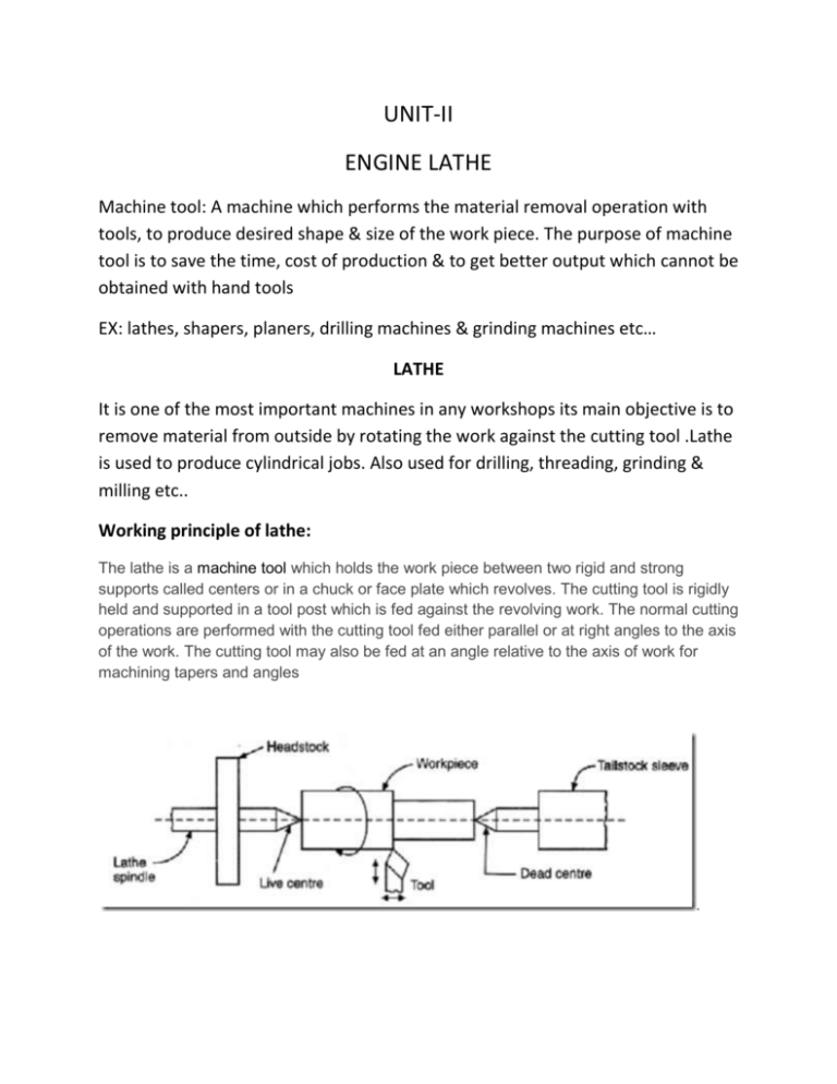
UNIT-II ENGINE LATHE Machine tool: A machine which performs the material removal operation with tools, to produce desired shape & size of the work piece. The purpose of machine tool is to save the time, cost of production & to get better output which cannot be obtained with hand tools EX: lathes, shapers, planers, drilling machines & grinding machines etc… LATHE It is one of the most important machines in any workshops its main objective is to remove material from outside by rotating the work against the cutting tool .Lathe is used to produce cylindrical jobs. Also used for drilling, threading, grinding & milling etc.. Working principle of lathe: The lathe is a machine tool which holds the work piece between two rigid and strong supports called centers or in a chuck or face plate which revolves. The cutting tool is rigidly held and supported in a tool post which is fed against the revolving work. The normal cutting operations are performed with the cutting tool fed either parallel or at right angles to the axis of the work. The cutting tool may also be fed at an angle relative to the axis of work for machining tapers and angles . Specifications of lathes: 1) Swing diameter: Largest diameter of work that can be effectively used for machining. It is twice the height of the centre measured from the lathe bed. 2) Distance between the centres:It is maximum length of the work that can be effectively used for machining between the head stock & tail stock. 3) Height of the centers: It is the height of the axis of the lathe measured from the lathe bed. 4) Length of the bed: It is the length which specific the floor space occupied by the lathe. 5) Maximum Diameter of the bar: Maximum diameter of the work piece that can pass through the spindle of head stock. Width & depth of the bed, Range of spindle speed, size of tool post, number of feeds Types of lathes Speed lathes: It consists of a bed, headstock, tail stock, & tool post mounted on a adjustable slide. There is no feed box, lead screw or a conventional type of carriage. In this High spindle speed are obtained which usually range from 1200 to 3600 rpm. As the tool s controlled by hand the depth of cut & thickness of chip is very small. Light cuts & high speed necessitate the use of this type of machine where cutting force is minimum such as in wood working, spinning, centering, polishing, etc.., Engine late (or) Centre lathe: It is similar to the speed lathe as it has all basic parts eg bed, headstock & tail stock. But its head stock of an engine lathe is much more robust in construction & its contain additional mechanism for driving the lathe spindle at multiple speed. These are classified according to various designs of the head stock & method of transmitting power to the machine. If its receives its power from an over head line shaft is a belt drive lathe. If it receives its power from an individual motor integral with the machine s called a motor driven lathe. A geared head lathe gets its power from a constant speed motor & all the speed changes are obtained by shifting a various gears located in head stock. Bench lathe: Small machine mounted on a bench. It has all the parts of an engine lathe or speed lathe & it performs all the operations its only difference being in the size. Used for small & precision work. Tool room lathe: It is similar to engine lathe in this the spindle speed ranging from very low to a quite high speed up to 2500 rpm This is equipped because other things with a chuck, taper turning attachment, drawn in collect attachment, thread chasing dial ,reveling attachment , steady & rest follower, pump coolant etc.. Used for precision work on tools, dies, gauges & in machining work where accuracy is needed. Costlier than the engine lathes of same size. Capstan & turret lathe: Developed by engine lathe are used for production work. In this lathe the tail stock is replaced by a hexagonal turret on which multiple tools may be fitted & fed into a work n proper sequence. Advantage is that several different operations can be done on a work piece without resetting of work or tool is produced in minimum time. Special purpose lathe: Wheel lathe is made for finishing the journals & turning the tread on rail road car & locomotive wheels. Gap bed lathe used for swing extra large diameters pieces. T lathe are used for machining of rotors for jet engines. Axis of lathe bed is at right angles to the axis of the head stock spindle is form of a “T”. Duplicating lathe is one for duplicating the shape of a flat or round template on to work piece. Automatic lathe: These are high speed, heavy duty, mass production lathes with complete automatic control. Changing of tools, speeds & feeds are also done automatically. An operator who has to look after 5 or 6 & automatic lathe at a time because all the operation are done automatically. FUNCTIONS OF LATHE PARTS: 1. Bed: The bed is a heavy, rugged casting in which are mounted the working parts of the lathe. It carries the headstock and tail stock for supporting the work piece and provides a base for the movement of carriage assembly which carries the tool. 2. Legs: The legs carry the entire load of machine and are firmly secured to floor by foundation bolts. 3. Headstock: The headstock is clamped on the left hand side of the bed and it serves as housing for the driving pulleys, back gears, headstock spindle, live centre and the feed reverse gear. The headstock spindle is a hollow cylindrical shaft that provides a drive from the motor to work holding devices. 4. Gear Box: The quick-change gear-box is placed below the headstock and contains a number of different sized gears. 5. Carriage: The carriage is located between the headstock and tailstock and serves the purpose of supporting, guiding and feeding the tool against the job during operation. The main parts of carriage are: a).The saddle is an H-shaped casting mounted on the top of lathe ways. It provides support to cross-slide, compound rest and tool post. b).The cross slide is mounted on the top of saddle, and it provides a mounted or automatic cross movement for the cutting tool. c) The compound rest is fitted on the top of cross slide and is used to support the tool post and the cutting tool. d) The tool post is mounted on the compound rest, and it rigidly clamps the cutting tool or tool holder at the proper height relative to the work centre line. e) The apron is fastened to the saddle and it houses the gears, clutches and levers required to move the carriage or cross slide. The engagement of split nut lever and the automatic feed lever at the same time is prevented she carriage along the lathe bed. 6. Tailstock: The tailstock is a movable casting located opposite the headstock on the ways of the bed. The tailstock can slide along the bed to accommodate different lengths of work piece between the centers. A tailstock clamp is provided to lock the tailstock at any desired position. The tailstock spindle has an internal taper to hold the dead centre and the tapered shank tools such as reamers and drills. TAPER TURNING METHODS: Taper turning is the process of producing taper on a work piece. The taper may be external or internal according to the requirements. The various method used for taper turning operations are. 1. Tail stock set over method 2. Compound Rest method 3. Taper turning attachment 4. Taper turning with a form tool Work holding Devices for Lathes: Many different devices, such as chucks, collets, faceplates, drive plates, mandrels, and lathe centers are used to hold and drive the work while it is being machined on a lathe. Work pieces can be held by various methods Work piece mounted between centers Work piece mounted within a single chuck Work piece mounted within a collet Work piece mounted on a faceplate Work piece mounted on rest follower a) Steady rest follower b) Follower rest Three Jaw chuck: It usually has three jaws, the jaws are moved simultaneously within the chuck Four Jaw chuck: This is independent chuck generally has four jaws , which are adjusted individually on the chuck face by means of adjusting screws Magnetic chuck: Thin jobs can be held by means of magnetic chucks. Face plates: The face plate is used for irregularly shaped work pieces that cannot be successfully held by chucks or mounted between centers Mandrels: A work piece which cannot be held between centers because its axis has been drilled or bored and which is not suitable for holding in a chuck or against a faceplate is usually machined on a mandrel. Collet chuck : Collet chuck is used to hold small work pieces. Steady Rest: It is consists of a C.I base which may be slide on the lathe bed ways & clamped at any desired position where a support is necessary. It consists of three jaws on the steady rest, two on the lower base & one is on the upper frame Follower Rest: It consists of a ’C’ like casting having two adjustable jaws support the work piece. 3 JAW CHUCK FACE PLATE 4 JAW CHUCK CAPSTAN & TURRET LATHES: It consists of bed, all geared headstock, & saddle on which a four station tool post is mounted to hold four different tools. In capstan or turret lathe there is no tail stock, but in its place a hexagonal turret is mounted on a slide which rests upon the bed. All the six faces of the turret can hold six or more number of different tools. The special characteristics of a capstan or turret lathe enables it to perform a series of operation such as turning, drilling, boring, thread cutting, reaming, necking, chamfering, cutting off & many other operations in minimum time. CAPSTAN & TURRET LATHE Specifications of Capstan & turret lathes: In case of horizontal machine Maximum dia of job to be turned Maximum dia of bar to be passes from head stock spindle In case of vertical machine Maximum dia of job that can turned without the side head Maximum dia of job that can be machined with side head Rotating table diameter. Other specifications like range of feed rates, power of main drive motor, spindle speed, total weight of the machine & overall dimensions. Classification of turret lathes 1 Horizontal turret lathes RAM type Saddle type 2 Vertical turret lathes 3 Numerically controlled (N/C) turret lathes 1 Horizontal type RAM type turret lathe or capstan type : Consists of a ram or slide mounted on the saddle & is free to move the guide ways provided on the saddle. Slide consists of a hexagonal turret carrying various tools on it. Saddle is moved & adjusted to the required position & the feed to the tool is given by moving the slide on the saddle. Used for small to medium sized works & is so named because of the use of ram or slide. Speed varies from 50 to 400 rpm depending upon the size. SADDLE type or turret lathe: It consists of turret head mounted directly on the saddle. For feeding to the tool the saddle has to moved forwards & the turret had its automatically indexed during the backward stroke to bring the required tool for next operation. Speed varies from 20 to 1500 rpm. 2 Vertical turret lathes: It consists of a circular table mounted on heavy base , vertical column carrying a cross rail which carries a saddle & turret head. Table rotates about its vertical axis & carries slots for claiming the work piece. Table may also carry chucks on it The side of the machine is usually provided with a square turret for machining the work from sides. During operation the cross rail moved up & down & provided by moving the saddle up & down vertically & to & fro along the cross rail. The feeding can be done by hand or by power. The side way operations can be performed simultaneously or separately depending upon the requirement. It is generally used for larger or heavier work as it provides very robust support to the work. Numerically controlled (N/C) turret lathes: Sets up and operates numerically controlled horizontal lathe to perform machining operations, such as turning, boring, facing, and threading parts, such as castings, forgings, and bar stock: Reads process sheets, blueprints, and sketches of part to determine machining to be done, dimensional specifications, set up, and operating requirements. Inserts beginning point of tape in reading head of control unit. Mounts workpiece between centers, in chuck, or to faceplate, manually or using hoist. Selects and installs preset tooling in tool posts, turrets or indexing heads, and automatic-tool-change magazine, in sequence specified on process sheet. Depresses buttons, toggles, or sets tape and starts machining operation. Observes numerical displays on control panel and compares with data on process sheet to verify dimensional adjustments, feed rates, and speeds of machining cuts. Turns dials and switches to override tape control and correct machine performance, applying practical knowledge of lathe operation. Inspects first-run piece and spot-checks succeeding pieces for conformance to specifications, using micrometers and precision dial gauges. Studies job packet and organizes materials for next run during automatic tape-controlled cycles to shorten changeover time. May set tools before positioning them in lathe, using precision gauges and instruments. May set up and operate another machine tool during tape-controlled machining cycles. May machine nonmetallic materials. May be designated by type of lathe operated as Engine Lathe Operator, Numerical Control; Turret Lathe Operator, Numerical Control. Work holding devices in CAPSTAN & TURRET LATHE 1 Jaw chuck Self centering chuck Independent chuck Combination chuck Air operated chuck 2 Collect chucks Push out type Draw in type Dead length type Operations performed on turret & capstan lathe: Turning Taper turning Facing Drilling Boring Reaming Threading Chamfering Knurling Parting off Tool holding device: Straight cutter holder Plain or adjustable angle cutter holder Multiple cutter holder Offset cutter holder Slide tool holder Knee tool holder Tap holder Die holder V steady box tool holder.
