Scan back with dry objective
advertisement
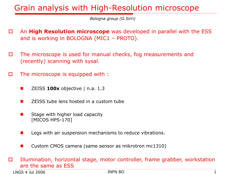
Grain analysis with High-Resolution microscope Bologna group (G.Sirri) An High Resolution microscope was developed in parallel with the ESS and is working in BOLOGNA (MIC1 – PROTO). The microscope is used for manual checks, fog measurements and (recently) scanning with sysal. The microscope is equipped with : ZEISS 100x objective | n.a. 1.3 ZEISS tube lens hosted in a custom tube Stage with higher load capacity [MICOS HPS-170] Legs with air suspension mechanisms to reduce vibrations. Custom CMOS camera (same sensor as mikrotron mc1310) Illumination, horizontal stage, motor controller, frame grabber, workstation are the same as ESS LNGS 4 Jul 2006 INFN BO 1 Measurements of the optical resolution: star test Star test: diagnostic tool which consists in the observation of the image of a point source of light (also known as Point Spread Function (PSF) of the objective) from the specimen projected by the microscope objective onto the camera sensor plane. In a perfect aberration-free optical system the image will be a very close approximation to the diffraction pattern rings Aberrations enlarge the Airy disk and produce a spot with variable form and photometric profile (circle of least confusion). This enlargement reduces the resolving power both in the lateral and in the axial directions. LNGS 4 Jul 2006 INFN BO 2 Nikon 50x ZEISS 100x Z (micron) 4 3 3 2 2 1 1 0 Circle of least confusion 0 -1 -1 Z ≈ 1 micron -2 -2 -3 -3 [custom setup: camera 50 mm below the specific coniugate] Circle of least confusion Z ≈ 5 micron X, Y ≈ 1 micron -4 X, Y ≈ 0.2 micron -6 NEGATIVE IMAGES LNGS 25 May 2005 -8 G. Sirri – INFN BO 3 Image formation The grain image is the space convolution between the grain surface and the P.S.F. . If our “object” size (grain Ø ≈0.6-0.8 micron) is smaller than the “circle of least confusion” : the geometrical image of the grain is smaller than the “circle of least confusion” and consequeltely its size is not proportional to the object (impossible to observe little differences in size) as smaller the object, as brighter the image Since the horizontal dimension of the circle of least confusion is 0.2 microns, this microscope is able to measure the grain size. LNGS 4 Jul 2006 INFN BO 4 Acquisition, analysis … and credits We used libACQ, a test library developed by I. Kreslo (Bern) and installed with the help of V. Tioukov (Naples). Each image grabbing is triggered by stage controller Output in libEdb format (FEDRA) Mean grey level of the clusters is also stored 100 levels per emulsion layer Image size: 0.5 Megapixel Magnification: 0.118 micron/pixel Several views in the whole emulsion sheet Analysis with an improved version of the Fedra Grain Analysis library (by V. Tioukov). limit for the clusters area >= 5 Vertical length of a grain >= 3 layers Two samples: Nov. 2004 (vertex location CERN test beam) June 2006 (cosmic rays exposure at LNGS) Grain Size = cluster area at center grain LNGS 4 Jul 2006 INFN BO z cluster eZ eZ0 grains g 5 Stability of the algorythm (Vertex Loc. nov04,br7,pl8) sublayer near the surface sublayer near the base Red = top Blue = bottom LNGS 4 Jul 2006 INFN BO 6 Mean grain area profile 100X ESS (expansion filter) ESS Nov 2004 June 2006 LNGS 4 Jul 2006 INFN BO 7 Cluster area profile (cut: area>2) (Vertex Loc. nov04, br7, pl8) Red = top Blue = bottom (cosmic rays, jun06, pl33) LNGS 4 Jul 2006 INFN BO 8 Grey level horizontal profile Grey level (cosmic rays, jun06, pl33) FWHM ≈ 5 pixel ≈ 0.6 micron X (1 pixel = 0.118 micron) LNGS 4 Jul 2006 INFN BO 9 Grey level vertical profile (negative image) (cosmic rays, jun06, pl33) (Vertex Loc. nov04, br7, pl8) Red = top Blue = bottom LNGS 4 Jul 2006 sublayer near the surface sublayer near the base INFN BO 10 Grain Size vertical profile Ø 0.72 micron (Vertex Loc. nov04, br7, pl8) Red = top Blue = bottom Ø 0.62 micron Ø 0.69 micron (cosmic rays, jun06, pl33) Ø 0.59micron LNGS 4 Jul 2006 INFN BO 11 Conclusions The grains of two sample were measured with a high resolution microscope equipped with 100x Zeiss objective. Nov. 2004 (vertex location test beam exposure at CERN) June 2006 (cosmic rays exposure at LNGS) Grain size: maybe -5% smaller, but we shuold better estimate the uncertainty related to threshold set-up and illumination uniformity ) At present the only evidence is for different thickness of the emulsion layers (35-40 micron for nov. 2004 and 55-60 for june 2006). Further investigation are needed. LNGS 4 Jul 2006 INFN BO 12 Further test with sysal MIC3 (sysal): Thr 400 500 600 700 800 900 GS (2004) 6.2 5.7 5.3 5.0 4.7 4.3 GS (2006) 5.8 5.4 5.0 4.7 4.4 4.1 GS (2004) 11.3 10.3 9.7 9.1 8.5 (expansion filter) GS (2006) LNGS 4 Jul 2006 4.9 INFN BO (27’ development) 13
