LAB: Laboratory Techniques
advertisement
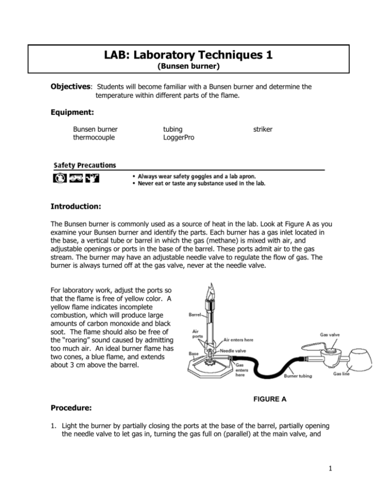
LAB: Laboratory Techniques 1 (Bunsen burner) Objectives: Students will become familiar with a Bunsen burner and determine the temperature within different parts of the flame. Equipment: Bunsen burner thermocouple tubing LoggerPro striker Introduction: The Bunsen burner is commonly used as a source of heat in the lab. Look at Figure A as you examine your Bunsen burner and identify the parts. Each burner has a gas inlet located in the base, a vertical tube or barrel in which the gas (methane) is mixed with air, and adjustable openings or ports in the base of the barrel. These ports admit air to the gas stream. The burner may have an adjustable needle valve to regulate the flow of gas. The burner is always turned off at the gas valve, never at the needle valve. For laboratory work, adjust the ports so that the flame is free of yellow color. A yellow flame indicates incomplete combustion, which will produce large amounts of carbon monoxide and black soot. The flame should also be free of the “roaring” sound caused by admitting too much air. An ideal burner flame has two cones, a blue flame, and extends about 3 cm above the barrel. FIGURE A Procedure: 1. Light the burner by partially closing the ports at the base of the barrel, partially opening the needle valve to let gas in, turning the gas full on (parallel) at the main valve, and 1 striking the striker about 5 cm above the top of the barrel until it lights. If it does not light within a few seconds, turn the gas off, wait a few minutes and try again. 2. Adjust your flame with the main valve until it is about 3 cm high. 3. Try completely closing the ports at the base of the burner. Note on your data sheet what effect this has on the flame. 4. Now adjust your supply of air until you have a quiet, steady flame with a sharply defined, light blue inner cone. This adjustment gives the highest temperature possible with your burner. 5. Place the lit burner aside as you complete steps 6 thru 8. (Be careful!) 6. One group member must log on to the computer. 7. Connect the thermocouple to the Go! Link Interface. 8. Double click on the Logger Pro icon on the desktop. The program should open up with a graph and data table. 9. Place the end of the thermocouple into the different parts of the flame as show in Figure B. Be careful to only put the metal portion of the thermocouple in the flame. Leave the thermocouple in that position for about 30 s and note the highest temperature reading for that position. The temperature is shown in the bottom left of the screen. Record the temperature readings for all positions in the diagram located on the data sheet. You may use the data sheet to record any other important observations. FIGURE B 10. Turn off the flame. 11. Close the LoggerPro program and log off the computer. 12. Return everything to its original location. 13. Have your teacher check your lab station and stamp your lab. 14. Now you can remove your goggles! 15. Complete the Questions/Analysis section on your data sheet. Be sure to answer in complete sentences (when applicable). 2 Teacher Notes On every lab table: Bunsen burner GoLink Thermocouple striker (should be in lab drawer) Comments: note burn hazard make sure GoLinks and thermocouples are accounted for when lab is done 3

