Technical
Paper
Do Organic Amines have a Role in the
Treatment of High Purity Boiler Feedwater?
Author: James Robinson
Abstract
Organic amines have been widely used to treat high-purity boiler feedwater since at least the 1940s. Although notable benefits have been derived, some consider the use of these amines to be risky. In addition,
the use of organic chemicals for boiler feedwater treatment often causes steam and condensate cation
conductivity levels to exceed current power industry guidelines. The benefits that can be derived and questions concerning the use of both neutralizing and filming amines are presented to help plant operators assess the potential value to be gained from using these amines in their systems.
Volatile Alkaline Treatments
Volatile alkaline treatments such as ammonia and neutralizing amines are used to elevate feedwater and
condensate pH in nearly all high-purity boiler feedwater systems. Some commonly used neutralizing amines
are morpholine, cyclohexylamine (CHA), diethylaminoethanolamine (DEAE) methoxypropylamine (MOPA) and
ethanolamine (ETA).
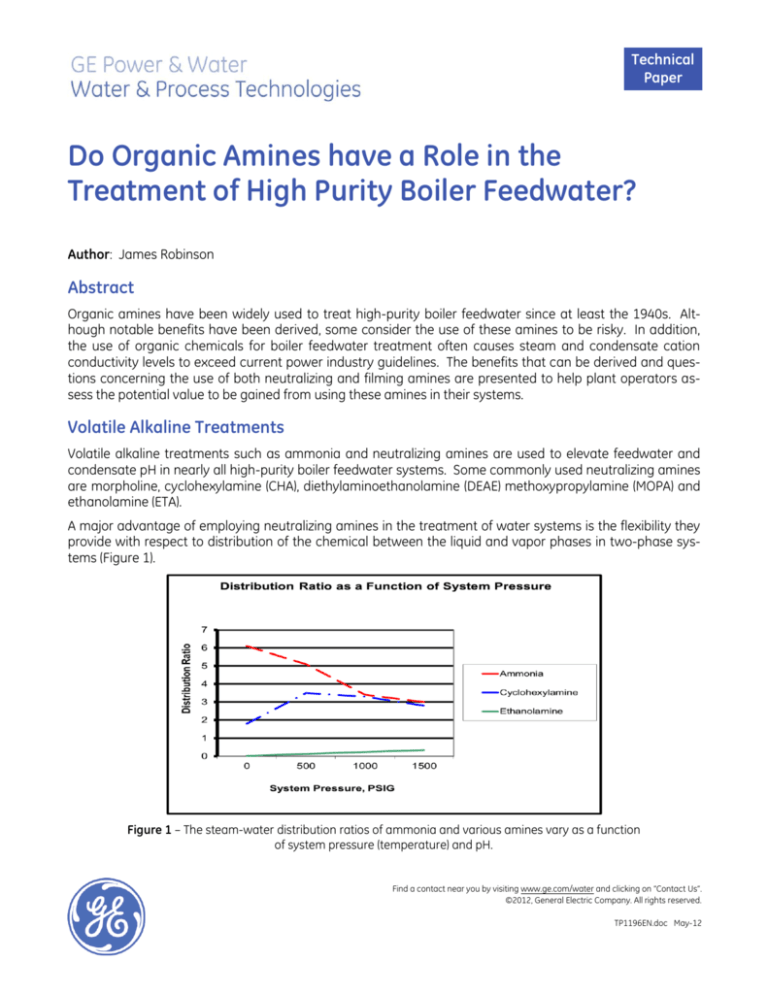
A major advantage of employing neutralizing amines in the treatment of water systems is the flexibility they
provide with respect to distribution of the chemical between the liquid and vapor phases in two-phase systems (Figure 1).
Figure 1 – The steam-water distribution ratios of ammonia and various amines vary as a function
of system pressure (temperature) and pH.
Find a contact near you by visiting www.ge.com/water and clicking on “Contact Us”.
©2012, General Electric Company. All rights reserved.
TP1196EN.doc May-12
Also, the high temperature in most parts of the boiler-steam system affects the temperature of the water
under operating conditions. Compared to ammonia, certain amines are better able to maintain alkaline pH
levels at the temperature of the water in steam generators (Figure 2).
Increase of pH at Temperature Compared to that
of Pure Water as a Function of Boiler Operating
Pressure When pH at 25 C is Adjusted to 9.0 with
Various Alkalizing Treatments
pH Increase Over Pure Water
1.4
1.2
1
Ammonia
0.8
Cyclohexylamine
0.6
Ethanolamine
0.4
0.2
0
0
500
1000
1500
System Pressure, PSIG
48
4/26/2011
Figure 2 – The effect of boiler pressure (temperature) on pH at temperature when otherwise pure water
is adjusted to a pH 9.0 at 25C with various volatile alkalizing chemicals.
Low-Pressure Evaporators in Heat Recovery Steam Generators
Many low-pressure (LP) evaporators in the heat recovery steam generators (HRSGs) of gas turbines are the
source of feedwater for the intermediate-pressure (IP) and high-pressure (HP) evaporators and for the steam
attemperating water. Consequently, the traditional chemicals used to control pH in low-pressure boilers,
phosphate and caustic, cannot be used in these LP evaporators -- so volatile chemicals must be relied upon
for pH control. Partially as a result of this inability to use phosphate and caustic in the LP evaporators, numerous flow-accelerated corrosion (FAC) problems have been encountered.
While some FAC problems are observed in the economizer inlet and other single-phase flow areas of the
evaporator, many are in the two-phase flow areas, such as the outlet ends of riser tubes and the steam separating equipment (Figure 3). Although fluid velocity and metallurgy are major factors in this metal wastage,
the pH of the liquid phase also has a significant effect. All else being equal, the lower the pH of the liquid
phase the greater the metal wastage. Since the vapor-liquid distribution and the at-temperature basicity of
the volatile alkaline treatment affect the pH of the liquid in the two-phase flow regions of the LP evaporator,
the amount of metal wastage in this area is also affected.
Page 2
Technical Paper
25
© 2010, General Electric Company
Figure 3 – FAC caused serious damage to this low-pressure evaporator steam separator.
To illustrate the effects of the steam-water distribution ratio and the at-temperature basicity of volatile alkaline treatments in LP evaporators, models were developed using Water & Process Technologies Computer
Modeling System (CMS)1 software. To develop the models, the CMS program calculates the steam-water distribution constants and acid dissociation constants of the feedwater contaminants and alkalizing agents at
the operating temperature of the evaporator. It then uses flow data to project the distribution of the constituents in the water and steam phases and calculates the pH of each stream at both the temperature of the
system (pHt) and at 25C (pH25C).
For the purposes of this illustration, an LP evaporator model that converts 10 percent of the feedwater into
100 psig (700kPa) steam and riser tubes that develop a steam-to-liquid weight ratio of 0.1 was used. Figures
3a through 3d show the projected pHt and pH25C developed at various locations in the LP evaporator when
ammonia or ETA is fed to the feedwater. The projected chemistry of each of the LP evaporator streams is
provided in Tables 1a through 1d.
Figure 4a shows that when ammonia is used to control the feedwater pH25C at 9.2, the expected pH at temperature in the liquid exiting the riser tube is 6.4. By comparison, Figure 4b shows that when ETA is used to
control the feedwater pH25C at 9.2, the expected pH at temperature in the liquid exiting the riser tube is 6.7.
Although this 0.3 unit difference in pH does not seem large, experience has shown that it is enough to dramatically reduce FAC problems in many systems. To develop the same 6.7 pHt in the liquid exiting the riser
tube when using ammonia, the feedwater pH25C must be increased to 9.6, as shown in Figure 4c. Dooley
and Anderson have suggested that the pH25C should be at least 9.8 to control two-phase FAC when ammonia
is used.2 This is to boost the pH at temperature one full unit above that of pure water, which is 5.8 at 100 psig
(700kPa)
Technical Paper
Page 3
Figure 4a – The use of ammonia to control LP feedwater pH 25C at 9.2 often results in FAC in riser tubes
Figure 4b – The use of ETA to control LP feedwater pH25C at 9.2 usually controls FAC in riser
tubes. However, the use of ETA alone can produce a low pH in the condensed steam.
Page 4
Technical Paper
Figure 4c – The use of ammonia to control LP feedwater pH 25C at 9.6 usually controls FAC in riser tubes. However, this
results in nearly 10 ppm of ammonia in the steam, making it unsatisfactory for many uses.
Figures 4b and 4c show that the use of ETA or ammonia alone may not provide satisfactory results throughout the system. The use of ETA alone may effectively protect the LP evaporator riser tubes from FAC, but result in low steam pH. By contrast, feeding enough ammonia to control FAC in the LP evaporator riser tubes
may cause excessive ammonia in the steam. For these systems, a blend of amines or ammonia and an
amine may prove desirable. The model in Figure 4d illustrates how a blend of ETA and ammonia can provide
a better pH balance throughout the LP evaporator.
Figure 4d - A blend of ETA and ammonia produces a nearly uniform pH throughout the LP system.
Technical Paper
Page 5
High-Pressure Evaporators in Heat Recovery Steam Generators
Another advantage of organic amines is the ability to provide protection to high-pressure (HP) evaporators
against acidic feedwater contamination. HP evaporators are often treated with either all volatile treatment
(AVT) or low-level phosphate-caustic treatment. When ammonia is used for feedwater pH control, these
treatments provide very limited protection against feedwater contamination.
This is illustrated in Figure 5, which depicts a model of the HP evaporator developed using CMS. This model
evaporator operates at 1500 psig with 0.5 percent blowdown. The feedwater pH is maintained at 9.4 by the
addition of a volatile alkalizing agent. This normally very high purity evaporator feedwater would have a cation conductivity of 0.12 S /cm due to the presence of 20 ppb carbon dioxide. As a result of additional contamination in the form of 5 ppb of acidic chloride, the model evaporator feedwater cation conductivity is
increased to 0.17 S /cm.
Figure 5 - HP evaporator with 5 ppb acidic chloride (cation conductivity of 0.17 S/cm)
contamination of the boiler feedwater.
Since much on-load corrosion of 1500 psig evaporators is due to underdeposit corrosion (Figure 6), CMS
models were designed to show the effect of different treatment chemistries on pH in both the bulk boiler water and boiler water that has been concentrated 10 fold beneath a deposit. This information is presented in
Figures 7a through 7d.
Page 6
Technical Paper
Figure 6 – Under deposit corrosion is the main cause of on-load high-pressure boiler tube failures.
Figures 7a and 7b show the projected results for all volatile treatment (AVT) with ammonia and ETA, respectively. Figure 7a shows that with ammonia treatment, although the pH25C of the bulk boiler water is 8.3, the
pHt is 5.0, well below the pHt of 5.7 for pure water. In addition, the concentrated water beneath the deposit is
projected to be highly corrosive, with a pHt of 3.8.
By contrast, in the ETA treated system, Figure 7b shows that the bulk boiler water pH25C is projected to be 9.6
and the pHt is projected to be 6.0, slightly above that of pure water at this temperature. The pHt of the concentrated water beneath the deposit is projected to be 5.3. Although this is still not optimum, it is significantly
better than the pHt of 3.8 that is projected for the ammonia-treated system.
Figure 7a – The pH at temperature is acidic in both the bulk boiler water and beneath a deposit in a 1500 psig boiler
tube with ammonia-based AVT feedwater treatment, when 5 ppb of acidic chloride contamination (cation conductivity
of 0.17 S/cm) is in the boiler feedwater.
Technical Paper
Page 7
Figure 7b – The pH at temperature is slightly alkaline in the bulk boiler water and slightly acidic beneath a deposit in a
1500 psig boiler tube with ETA based AVT treatment when 5 ppb of acidic chloride contamination (cation conductivity of
0.17 S/cm) is in the boiler feedwater.
Figures 7c and 7d illustrate the advantages of using ETA compared to ammonia for feedwater pH control
under the following conditions: The boiler water is treated with 0.5 ppm of trisodium phosphate and 0.5 ppm
of sodium hydroxide, and the feedwater is contaminated with 5 ppb of acidic chloride.
Figure 7c shows that with ammonia feedwater treatment, the 5 ppb of feedwater chloride produces an acidic pHt of 5.4 in the bulk boiler water and 4.4 beneath the deposit. Acidic corrosion is very likely under these
conditions even though the bulk boiler water has an alkaline pH25C of 8.4.
By contrast, as illustrated in Figure 7d, if ETA is used for feedwater treatment, the bulk boiler water pHt is projected to be 6.3, which is slightly alkaline, and the pHt of the water concentrated beneath the deposit is projected to be only slightly acidic at 5.7.
Figure 7c– The pH at temperature is acidic in both the bulk boiler water and beneath a deposit in a 1500 psig boiler
tube with low-level trisodium phosphate, caustic and ammonia feedwater treatment, when 5 ppb of acidic chloride
contamination (cation conductivity of 0.17 S/cm) is in the boiler feedwater.
Page 8
Technical Paper
Figure 7d– The pH at temperature is slightly alkaline in the bulk boiler water and slightly acidic beneath a deposit in a
1500 psig boiler tube with low-level trisodium phosphate, caustic and ETA feedwater treatment, when 5 ppb of acidic
chloride contamination (cation conductivity of 0.17 S/cm) is in the boiler feedwater.
The information extracted from Figures 7b and 7c and presented in Table 3 of the appendix shows that at
the model conditions, the AVT treatment using ETA for feedwater pH elevation provides better protection
from acidic chloride corrosion than does low-level phosphate and caustic treatment when ammonia is used
for feedwater pH control. The pHt of the bulk boiler water is maintained at 6.0 with the ETA-based AVT
treatment, while it drops to 5.4 when using low-level phosphate and caustic treatment with ammonia for
feedwater pH control. Beneath the deposit, the pHt of the AVT treatment using ETA becomes slightly acidic
at 5.7. By comparison, the pHt beneath the deposit with the low-level phosphate, caustic and ammonia
treatment is 4.4.
Boilers designed with adequate circulation so that phosphate hideout is not an issue can obtain significantly
greater protection from acidic chloride contamination by maintaining an increased level of trisodium phosphate in the boiler water. As shown in Figure 7e, the feed of trisodium phosphate to maintain 6 ppm of
phosphate in the boiler water maintains alkaline water with a pHt of 7.7 in the bulk boiler water and 8.7 when
concentrated 10 times beneath a deposit, in the presence of 5 ppb acidic chloride feedwater contamination.
The increased protection from acidic corrosion provided by ETA or increased TSP is afforded without the
need for adding caustic to the system, reducing the risk of steam system damage.
Technical Paper
Page 9
Figure 7e - The pH at temperature remains alkaline in both the bulk boiler water and beneath a deposit in a 1500 psig
boiler tube with 6 ppm of phosphate in the boiler water when the feedwater has 5 ppb of acidic chloride.
Filming Amines
Filming amines have been used almost as long as neutralizing amines to protect equipment by forming a
non-wettable film on metal surfaces. Figure 8 shows the protection polyamine application afforded corrosion coupons exposed to 100 ppb of oxygen at 230F (110C) for 7 days.4
Figure 8 – Filming amines form a non-wettable film on metal surfaces, providing protection against oxygen corrosion.
The above coupons were exposed to a filmer-neutralizer treatment and 100 ppb of dissolved oxygen in demineralized
water at 230F for seven days. The average corrosion rate was measured to be 0.23 mils/yr with no noticeable pitting
observed.
Page 10
Technical Paper
In the industrial sector, filming amines have been particularly useful for controlling 2-phase flow accelerated
corrosion and protecting equipment when it is out of service. Filming amines were applied to a limited number of electric power plants in the 1950s, with the following favorable results reported at Cincinnati Gas and
Electric5
1. “The film gives protection against carbon dioxide and oxygen corrosion.”
2. “Filming amine gives protection to systems used frequently for stand-by service because it offers
protection against oxygen which is often present in this type of service.”
3. “Filming amine has no adverse effects on copper and copper bearing alloys. It may offer protection to such alloys …”
And Arkansas Power and & Light6
1. “With filming-amine treatment well established, unit startup after a prolonged outage shows a
more rapid decrease in boiler water turbidity.”
2. “Residual film during the outage protects metal in the feedwater system from the corrosive effects of oxygen and other elements in the air.”
3. “Since filming-amine treatment started, a marked decrease in boiler sludge has been noted.”
More recently, First Energy Corp reported on the benefits they are currently experiencing using filming amine
treatment.7 Among the benefits noted were:
1.
“…this type of chemical control program can protect both iron and copper systems even when
exposed to oxidizing all volatile treatment and ammonia cycle conditions.
2. “Testing of this program also indicates a significant reduction in Fe2+, an indication of protection
against FAC.”
Based on the experience at these three utilities, it is anticipated filming amines can provide improved protection for those systems that cycle frequently.
Why are Organic Amines not more Widely Used in the Power Industry?
In spite of the benefits that can be derived by employing properly selected neutralizing amines, their use is
restricted from many power plant systems for numerous reasons. One major reason is the thermal decomposition of neutralizing amines in steam superheaters and reheaters. The amount of decomposition that
occurs depends on the particular chemicals used, the temperature of the superheat and reheat steam, and
the time of exposure at those temperatures.
Ammonia, carbon dioxide, acetate and formate are some of the most commonly formed decomposition
products. Carbon dioxide, acetate and formate have been of concern due to their potential for causing corrosion in the steam-condensate system and because of their masking effect on cation conductivity measurements. Ammonia formation is also of concern due to the increased potential for corrosion in systems
with copper alloys.
CORROSION CAUSED BY CARBON DIOXIDE AND ORGANIC ACIDS - Carbon dioxide is well known for the numerous acidic condensate corrosion problems it has caused in boiler systems with sodium zeolite softened
make-up water. On a much more limited basis, there have been reports of acidic organic contamination of
boiler feedwater also causing corrosion. While not all answers are known, investigations of these reports 3,
operating experiences reported by Carvalho8,9 and discussions from recent conferences have concluded that
the priority for control of carbon dioxide and organic acid corrosion is maintaining sufficient pH throughout
the system.10
CATION CONDUCTIVITY - Cation conductivity is widely used in the power industry to detect contamination of
condensate, feedwater and steam. It has proven very useful for identifying the presence of anions such as
chloride and sulfate in the condensate as the result of condenser tube leaks. However, it also provides an
undifferentiated indication when carbon dioxide, formate and acetate are also present. Consequently, this
makes cation conductivity a less effective tool for detecting the potentially more damaging chloride and
sulfate contaminants.
Technical Paper
Page 11
Turbine manufacturers usually specify a cation conductivity limit for the turbine inlet steam of less than 0.2
or 0.3 S/cm. In the absence of other contaminants, it takes 16 ppb (g/l) and 25 ppb (g/l) of chloride to
produce cation conductivity levels of 0.2 S/cm and 0.3 S/cm, respectively. Some manufacturers that
specify chloride levels have limits of 5 ppb (5 g/l), others as low as 3 ppb (g/l). Five ppb (g/l) of chloride
produces a cation conductivity level of approximately 0.09 S/cm when no other contaminant is present.
It can be readily seen that the specified cation conductivity limits do not assure that other limits such as
those for chloride or sulfate are met. At the same time, many personnel in cycling plants know well that carbon dioxide contamination makes meeting cation conductivity limits on startup difficult, if not impossible.
Consequently, there is a clear need for a more definitive monitoring tool, one that better quantifies the
known turbine corrodents such as chloride and sulfate.
Degassing can be used to expel carbon dioxide from the sample stream, eliminating its effect on cation conductivity. Therefore, degassed cation conductivity has increased sensitivity to chloride and sulfate contamination when carbon dioxide is present in the original sample. Consequently, this steam purity monitoring
methodology is gaining in popularity, especially in those plants in cycling service.
Turbine manufacturers have taken different positions with respect to degassed cation conductivity. One
manufacturer limits the use of degassed cation conductivity to the commissioning period. Another manufacturer allows higher cation conductivity if it is known to be caused by carbon dioxide.
Ion chromatography (IC) is a more direct approach to monitoring the strongly acidic anions, such as chlorides and sulfates, known to be of major concern. The relatively high cost of the analytical instrumentation
and the personnel attention required to operate it have curtailed the popularity of this approach.10
Although not experienced in the three previously reported case histories, filming amines have a reputation
for moving previously formed corrosion products from their original location to steam traps, instrument lines
and condensate polishers where they may foul the equipment. Consequently, while the application of filming
amines is expected to result in cleaner metal surfaces and reduced corrosion, some period of clean up may
be experienced before the full benefits of filming amine application are realized.
Conclusions
Organic amines have been used for decades and continue to be used to protect steam plant equipment and
maintain reliable, efficient plant operations. Their proper use can provide increased corrosion protection not
available through the use of inorganic chemicals alone. The authors have found that these organic treatments or their decomposition products have low corrosion risk as long as pH is adequately maintained
Thermal instability limits the application of organic chemicals, especially neutralizing amines in power plant
applications, because of the effect of the decomposition products on cation conductivity measurements.
This effect decreases the sensitivity of cation conductivity for detecting condenser tube leaks and often
boosts the steam cation conductivity above the steam turbine manufacturer’s specification.
The conundrum is that many avoid using organic chemical treatments because their use causes them to
exceed the turbine manufacturer’s steam cation conductivity limits. Yet, meeting those limits does not assure that potentially acidic species, such as chloride and sulfate, are within an acceptable range. In addition,
one of the most damaging potential steam contaminants, sodium hydroxide, is not detected by cation conductivity at all.
Improved criteria for steam purity and plant-friendly methods of monitoring those criteria are needed. For
now, plant operators must evaluate their own specific needs, compare those needs to the information available and select the treatment that is expected to provide the most value to their plant.
Page 12
Technical Paper
References
1. Robinson, J., “New Computer Modeling System Improves Condensate Treatment”, Corrosion Asia, Singapore, September, 1994
2. Dooley, B., Anderson, B., “HRSG Assessments Identify Trends in Cycle Chemistry, Thermal Transient Performance,” Power Plant Chemistry, March, 2009
3. Denk, J., Svoboda, R., “Stress Corrosion Cracking Due to Carbon Dioxide and Organic Impurities in the
Steam/Water Cycle” Power Plant Chemistry, July 2006
4. Crovetto, R., etal. “Research Evaluation of Polyamine Chemistry for Boiler Treatment: Corrosion Protection,” NACE Corrosion 2011, Houston, Texas
5. Galloway, E., Filming Amines Control Corrosion in Utility Plant Condensate System,” Corrosion, Volume
15, August, 1959
6. White, J.P., “Filming Amines Reduce Corrosion at Arkansas P&L,” Power, April, 1960
7. Verib, George J., “An Alternative Chemistry for Both Operational and Layup Protection of High-Pressure
Steam-Water Cycles Using an Organic Filming Amine”, Power Plant Chemistry, 2011, 13(5)
8. Carvalho, L, etal. “Cation Conductivity and Power Reliability – A 20 Plant Survey”, International Water
Conference, Pittsburgh, PA 2001
9. Carvalho, L, etal. “Is Cation Conductivity Monitoring Relevant For Today’s Combined Cycle Power Plant?
– Yet Another Case Study Says It Is Not”, IWC –06-30, International Water Conference, Pittsburgh, PA
2006
10. Mathews, J. A., “Challenges in Cycle Chemistry” Power Plant Chemistry, May, 2009
11. Newton, Beverly, et.al., “Fear and Loathing in a Combined Cycle Power Plant – Ion Chromatography in a
Box”, International Water Conference, 2004 Pittsburgh, PA
Technical Paper
Page 13
Appendix
Table 1a (Figure 4a) –LP Evaporator Steam Drum – 100 psig (700 kPa) – Steam Flow = 10% of Feedwater Flow - CO2
Contamination of Feedwater - Ammonia Treatment to Feedwater pH25C of 9.2
Feedwater
Blowdown
Riser
Steam
CO2, ppb (g/l)
3
<1
<1
30
NH3, ppb (g/l)
530
370
270
1990
Conductivity,
S/cm
4.4
3.4
2.7
10.1
Cation Conductivity, S/cm
0.06
pH @ 25C
9.2
9.1
9.0
9.6
pH @ T
6.6
6.5
6.4
6.9
0.16
Table 1b (Figure 4b) –LP Evaporator Steam Drum – 100 psig (700 kPa) – Steam Flow = 10% of Feedwater Flow – CO2
Contamination of Feedwater - MEA Treatment to Feedwater pH25C of 9.2
Feedwater
Blowdown
Riser
Steam
CO2, ppb (g/l)
3
<1
<1
30
ETA, ppb (g/l)
1550
1710
1830
83
Conductivity,
S/cm
3.9
4.2
4.5
0.22
Cation Conductivity, S/cm
0.06
pH @ 25C
9.2
9.2
9.3
7.8
pH @ T
6.6
6.6
6.7
5.9
0.16
Table 1c (Figure 4c) –LP Evaporator Steam Drum – 100 psig (700 kPa) – Steam Flow = 10% of Feedwater Flow – CO2
Contamination of Feedwater - Ammonia Treatment to pHt of 6.7 in Riser Tube
Page 14
Feedwater
Blowdown
Riser
Steam
CO2, ppb (g/l)
3
<1
<1
30
NH3, ppb (g/l)
2300
1460
950
9890
Conductivity,
S/cm
11.0
8.4
6.4
25.1
Cation Conductivity, S/cm
0.06
pH @ 25C
9.6
9.5
9.4
9.9
pH @ T
6.9
6.8
6.7
7.2
0.16
Technical Paper
Table 1d (Figure 4d) –LP Evaporator – 100 psig (700 kPa) – Steam Flow = 10% of Feedwater Flow –– CO2 Contamination
of Feedwater – ETA and Ammonia Treatment to pHt of 6.7 in Riser Tube
Feedwater
Blowdown
Riser
Steam
CO2, ppb (g/l)
3
<1
<1
30
ETA, ppb (g/l)
1200
1300
1400
100
NH3, (g/l)
300
200
130
1200
Conductivity,
S/cm
5.1
4.7
4.6
7.6
Cation Conductivity, S/cm
0.06
pH @ 25C
9.3
9.3
9.3
9.4
pH @ T
6.7
6.7
6.7
6.8
0.16
Table 2a (Figure 7a) – HP Evaporator – 1500 psig (10,500 kPa) – Blowdown = 0.5% of Feedwater Flow - CO2 and Chloride
Contamination of Feedwater – Ammonia Based AVT
Feedwater
Riser Tube
Under Deposit
CO2, ppb (g/l)
20
<1
<1
Chloride, ppb (g/l)
5
1,000
10,000
NH3, (g/l)
1,100
560
1,300
Conductivity, S/cm
5.1
4.7
98
Cation Conductivity,
S/cm
0.17
12
119
pH @ 25C
9.4
8.3
3.7
5.0
3.8
pH @ T
Table 2b (Figure 7b) – HP Evaporator – 1500 psig (10,500 kPa) – Blowdown = 0.5% of Feedwater Flow - CO2 and Chloride
Contamination of Feedwater – ETA Based AVT
Feedwater
Riser Tube
Under Deposit
CO2, ppb (g/l)
20
<1
<1
Chloride, ppb (g/l)
5
1,000
10,000
ETA, (g/l)
3,000
9,490
34,400
Conductivity, S/cm
6
12.8
39
Cation Conductivity,
S/cm
0.17
11.9
119
pH @ 25C
9.4
8.3
9.4
5.0
5.3
pH @ T
Technical Paper
Page 15
Table 2c (Figure 7c) – HP Evaporator – 1500 psig (10,500 kPa) – Blowdown = 0.5% of Feedwater Flow - CO2 and Chloride
Contamination of Feedwater – Ammonia Feedwater Treatment – Low-Level Phosphate and Caustic Treatment of the
Boiler Water
Feedwater
Riser Tube
Under Deposit
CO2, ppb (g/l)
20
<1
<1
Chloride, ppb (g/l)
5
1,000
10,000
NH3, ppb (g/l)
1,100
440
PO4, ppb (g/l)
500
5,000*
NaOH, ppb (g/l)
500
5,000
Conductivity, S/cm
5.1
5.9
66*
Cation Conductivity,
S/cm
0.17
14
138*
pH @ 25C
9.4
8.6
9.4
5.4
5.3
pH @ T
*Assumes phosphate remains soluble
Table 2d (Figure 7d) – HP Evaporator – 1500 psig (10,500 kPa) – Blowdown = 0.5% of Feedwater Flow - CO2 and Chloride
Contamination of Feedwater – ETA Feedwater Treatment – Low-Level Phosphate and Caustic Treatment of the Boiler
Water
Feedwater
Riser Tube
Under Deposit
CO2, ppb (g/l)
20
<1
<1
Chloride, ppb (g/l)
5
1,000
10,000
ETA, ppb (g/l)
3,000
8,600
24,700
PO4, ppb (g/l)
500
5,000*
NaOH, ppb ( g/l)
500
5,000
14
49*
14
138*
9.6
9.5
6.3
5.7
Conductivity, S/cm
6
Cation Conductivity,
S/cm
pH @ 25C
pH @ T
9.4
*Assumes phosphate remains soluble
Page 16
Technical Paper
Table 2e (Figure 7e) – HP Evaporator – 1500 psig (10,500 kPa) – Blowdown = 0.5% of Feedwater Flow - CO2 and Chloride
Contamination of Feedwater – Ammonia Feedwater Treatment – Trisodiumphosphate Treatment of the Boiler Water
Feedwater
Riser Tube
Under Deposit
CO2, ppb (g/l)
20
<1
1
Chloride, ppb (g/l)
5
1,000
10,000
NH, ppb (g/l)
1,100
360
130
PO4, ppb (g/l)
6,000
60,000*
NaOH, ppb (g/l)
0
0
Conductivity, S/cm
5.1
23
203*
Cation Conductivity,
S/cm
0.17
35
330*
pH @ 25C
9.4
8.6
4.1
5.4
4.4
pH @ T
Table 3 (Figures 7b and 7c) - AVT treatment with ETA provides better protection against acidic chloride corrosion than
low-level phosphate-caustic-ammonia treatment.
Treatment Program
pHt in Boiler Tube
pHt Beneath Deposit
Phosphate-NaOH-NH3
5.4
4.4
AVT - ETA
6.0
5.3
Technical Paper
Page 17

