Thermo-Fluids Lab
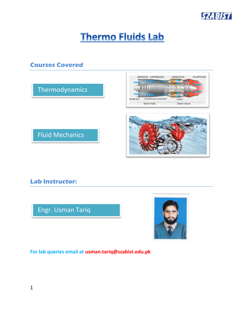
Courses Covered
Thermodynamics
Fluid Mechanics
Lab Instructor:
Engr. Usman Tariq
For lab queries email at usman.tariq@szabist.edu.pk
1
Contents
Temperature measurement and Calibration ........................................................ 9
Pressure and Vacuum Gage Calibration with Manometer .................................. 12
2
Fluid Friction Measurement Apparatus ......................................................... 16
Properties of Fluid and Hydrostatic Bench ..................................................... 18
3
Pictorial view
4
Thermodynamics Apparatus
Boyle’s Law
Objectives
To demonstrate the changes in gas temperature during compression and decompression.
To prove Boyle’s Law by experiment.
Description
Students use hand-operated pumps to increase or decrease the pressure in the left-hand cylinder which moves a ‘liquid piston’ of oil in the right-hand cylinder.
This piston compresses or decompresses a trapped column of air in the Test
Cylinder and then the students measure the volume for various pressures while waiting for the temperature to become constant. Finally, they do the required calculations and plot graphs to verify the Boyle’s Law.
5
Gay-Lussac’s Law
Objectives
To demonstrate change of pressure of a fixed volume of gas during heating.
To prove Gay-Lussac’s Law by experiment.
Description
The vessel holds a fixed volume of air surrounded by an insulated heater, controlled by an electronic temperature controller. Since air is a poor conductor of heat, therefore the temperature is not uniform inside. To overcome this, the apparatus measures temperature at different locations presented on the digital display along with the average temperature. The pressure inside the vessel is given by pressure transducer which can also be seen on the display. The temperature is noted for different set points and the corresponding pressure as well. To conclude, the theoretical relationship is verified by plotting the data on a graph and looking for the trend of proportionality.
6
Francis Turbine
Objectives:-
To determine the turbine characteristic curve produced by the turbine.
Description
Water from the hydraulic tank pumped into the inlet, and the input power is calculated through volume flow rate and the pressure, the load is applied by giving the shaft frictional resistance through spring balance and the difference is measured to determine the net load. The output power is determined through
RPM and the load. These characteristics are found for various loads and a characteristic curve is plotted for output power and efficiency against turbine speed at a constant flow rate. The characteristic curve is matched with the rough trend as the instructor will tell in the before the experiment.
7
Pelton Wheel Turbine
Objective
To determine the turbine characteristic curve produced by the turbine.
Description
“This hydraulic turbine has high efficiency for high heads as compared to Francis turbine.”
The above claim has to be confirmed before installing it to Practical applications.
The students follow the same procedure as for the Francis turbine. Both are then compared and the claim is checked to avoid later expensive mishaps.
8
Temperature measurement and Calibration
Objectives
Understand the main operating characteristics of temperature measurement devices such as resistor temperature detectors, thermistors, and thermocouples.
Be able to experimentally determine temperature curves for temperature measurement devices.
Description
It includes eight different temperature measurement devices and shows their characteristics and how to calibrate them against a standard. The built-in precision reference sensor works as an accurate temperature reference. A display shows the temperature from the reference sensor and the local
(barometric) pressure from the built-in pressure sensor.
9
Internal Combustion Engine
Objectives:-
View the different parts of IC ENGINE and understand how they work together to produce useful power output.
Description:-
Internal combustion engines are made from various parts. Students are first shown videos of IC Engine working and then they move to a disassembled engine to show them the parts and how they function in the real world to make our lives easier and more comfortable.
10
Bourdon Gauge Calibration
Objectives:-
To caliberate the Bourdon Guage against a standard applied pressure.
Description:-
Students note down the cross-sectional area of the piston which exerts pressure on the liquid transmitted to the gauge. Then, they add the masses and the applied pressure is calculated and compared with the reading of the gauge for various pressures. As a standard rule, if the error is with in ±5% of the actual applied pressure then it is safe for practical engineering applications.
11
Pressure and Vacuum Gage Calibration with Manometer
Objectives
Verify the pressure and vacuum guage caliberations through U-tube and inclined manometer.
Description:-
Students apply pressure through syringes and “T” Connections to U-tube manometer, inclined manometer and pressure gauge simultaneously so that error in the readings is minimized and the corresponding columns heights are noted for both manometers. Since the pressure in liquids is the function of vertical height in the direction of gravity, the vertical component is calculated and the difference is measured to calculate the difference in height and the applied pressure is determined. The applied pressure is compared to the readings of the gauge. Similar procedure is followed for the vacuum guage.
12
Fluid Mechanics Lab
Osborne Reynold’s Demonstration
Objectives
To compute Reynolds’s number (R).
To observe the laminar, transitional and turbulent flow.
To determine the Reynolds’s number (R)
To determine the upper and lower critical velocities at transitional flow.
13
Bernoulli’s Theorem Demonstration Unit
Objectives
To determine the discharge coefficient of the venturi meter
To measure flow rate with venturi meter
To demonstrate Bernoulli’s Theorem To determine the discharge coefficient of the venturi meter
To measure flow rate with venturi meter
To demonstrate Bernoulli’s Theorem
14
Energy Losses in Bends and Fittings
__________________________________________________________________
Objectives
Measuring the losses in the devices related to flow rate and calculating loss coefficients related to velocity head.
Comparing the pressure drop across each device.
15
Fluid Friction Measurement Apparatus
To determine the relationship between head loss due to fluid friction and velocity for flow of water through smooth bore pipes.
To confirm the head loss predicted by pipe friction equation associated with flow of water through a smooth bore pipe.
To determine the relationship between fluid friction coefficient and Reynolds’ number for flow of water through a pipe having a roughened bore.
To determine the head loss associated with flow of water through standard fittings used in plumbing installations.
To demonstrate the application of differential head devices in the measurement of flow rate and velocity of water in a pipe.
Hydraulic Bench
Determining Volumetric Flow Rate using Hydraulic Bench
16
Pipe Friction Apparatus
Objectives
17
Measurement of pressure loss for laminar and turbulent flow.
Determination of critical Reynolds’ number.
Head loss measurements using tube manometer and mercury U tube manometers.
Properties of Fluid and Hydrostatic Bench
Objectives
Measurements of density, specific gravity, viscoscity, pressure and humidity
Function and use of a hydrometer
Demonstration of fluid upthrust (Pascal’s Law)
Capillarity
Determination of center of pressure and metacentric height
Calibration of pressure gauge
18
