Class B
advertisement
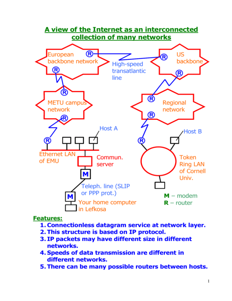
A view of the Internet as an interconnected collection of many networks European backbone network High-speed transatlantic line Host A Commun. server M M Teleph. line (SLIP or PPP prot.) Your home computer in Lefkosa US backbone METU campus network Ethernet LAN of EMU Regional network Host B Token Ring LAN of Cornell Univ. M – modem R – router Features: 1. Connectionless datagram service at network layer. 2. This structure is based on IP protocol. 3. IP packets may have different size in different networks. 4. Speeds of data transmission are different in different networks. 5. There can be many possible routers between hosts. 1 Addressing in TCP/IP networks 0 Bit order IP address netid Class 0 7 8 31 netid hostid 7 24 01 2 Class B hostid 32 bits 0 12 Class A 15 16 10 31 netid hostid 14 16 012 3 Class C 31 23 24 110 netid hostid 21 8 0123 4 Class D 1110 31 31 Multicast address 24 Examples: IP addr.=118.6.20.250 ; 11810=0111 01102 118 6 20 250 class A 32 bits IP addr.=193.17.40.78 ; 19310=1100 00012 class C 2 Subnet addressing (an example) 134.220.1.10 134.220.1.15 Server DNS Organization: netid=134.220 class B Subnet 134.220.1.0 134.220.1.1 Router 134.220.2.5 !!!! 134.220.2.2 Subnet 134.220.2.0 2 addresses for the router 3 Subnetworking in TCP/IP networks Subnetworking is the division of the normal range of host id’s into a number of subnetworks, with the reduced number of hosts on each subnetwork. An example: A company wants to install 400 TCP/IP hosts (computers). So class B network is necessary. Max. Desired Utilization= number of number of (400/65536)*100% = hosts hosts 0.6% Class B 65 536 400 Using a subnet mask: IP address with masking = (original IP address) AND (subnet mask) In our example: Binary Original IP address Subnet mask Network ID Host ID Dotted Decimal 10000001.10000010.01001111.01010101 129.130.79.85 11111111.11111111.11111110.00000000 255.255.254.0 10000001.10000010.01001110.00000000 129.130.78.0 00000000.00000000.00000001.01010101 0.0.1.85 Or 129.130.79.85/23 Number of 1’s in network mask Network ID = Orig. IP address AND Subnet mask Host ID = Orig. IP address AND NOT Subnet mask 4 Network byte order The purpose: to define a standard representation of data. Two types of ordering: The lowest memory address Byte 0 Big endian computers (Motorola 68000, ..) Most significant byte Byte 3 Little endian computers (Intel 286/386/..) The most sign. byte first Host A 3 2 1 1 0 Local representation of an integer in A 0 1 2 3 Network byte order (Big endian) 2 3 Integer 2 1 0 Integer The lowest memory address Host B 3 2 1 0 Local representation of an integer in B 5 Mapping IP addresses to physical address 1. Each host in the TCP/IP internet has a physical address on some network. 2. Each host . . . has an IP address (or a few IP addresses). 3. Physical address IP address. 4. Two hosts on a physical network can communicate only if they know each other’s physical network address. A Phys. Address PA IP address IA B PB, IB Network 1 C Network 2 Two phys. Addresses, two IP addresses The goal: higher-level programs must work only with IP address. 6 IP address and physical address FCS Frame from data link layer Data from appl. layer Error control TCP segment IP packet TCP header IP header Data link (Frame) header Sequence of bits in phys. layer (nonstructured) IP address Phys. addresses 7
