Lab 2.5.1: Basic Switch Configuration (warning: Microsoft virtual PC
may consume 2 mac addresses – one real, one simulated, PER host)
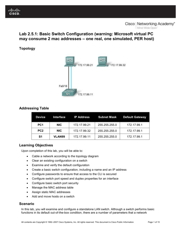
Topology
Addressing Table
Device
Interface
IP Address
Subnet Mask
Default Gateway
PC1
NIC
172.17.99.21
255.255.255.0
172.17.99.1
PC2
NIC
172.17.99.32
255.255.255.0
172.17.99.1
S1
VLAN99
172.17.99.11
255.255.255.0
172.17.99.1
Learning Objectives
Upon completion of this lab, you will be able to:
Cable a network according to the topology diagram
Clear an existing configuration on a switch
Examine and verify the default configuration
Create a basic switch configuration, including a name and an IP address
Configure passwords to ensure that access to the CLI is secured
Configure switch port speed and duplex properties for an interface
Configure basic switch port security
Manage the MAC address table
Assign static MAC addresses
Add and move hosts on a switch
Scenario
In this lab, you will examine and configure a standalone LAN switch. Although a switch performs basic
functions in its default out-of-the-box condition, there are a number of parameters that a network
All contents are Copyright © 1992–2007 Cisco Systems, Inc. All rights reserved. This document is Cisco Public Information.
Page 1 of 15
CCNA Exploration
LAN Switching and Wireless: Basic Switch Concepts and Configuration
Lab 2.5.1: Basic Switch Configuration
administrator should modify to ensure a secure and optimized LAN. This lab introduces you to the basics
of switch configuration.
Task 1: Cable, Erase, and Reload the Switch
Step 1: Cable a network.
Cable a network that is similar to the one in the topology diagram. Create a console connection to the
switch. If necessary, refer to Lab 1.3.1 on how to create a console connection.
You can use any current switch in your lab as long as it has the required interfaces shown in the topology.
The output shown in this lab is from a 2960 switch. If you use other switches, the switch outputs and
interface descriptions may appear different.
Note: PC2 is not initially connected to the switch. It is only used in Task 5.
Step 2: Clear the configuration on the switch.
Clear the configuration on the switch using the procedure in Appendix 1.
Task 2: Verify the Default Switch Configuration
Step 1: Enter privileged mode.
You can access all the switch commands in privileged mode. However, because many of the privileged
commands configure operating parameters, privileged access should be password-protected to prevent
unauthorized use. You will set passwords in Task 3.
The privileged EXEC command set includes those commands contained in user EXEC mode, as well as
the configure command through which access to the remaining command modes are gained. Enter
privileged EXEC mode by entering the enable command.
Switch>enable
Switch#
Notice that the prompt changed in the configuration to reflect privileged EXEC mode.
Step 2: Examine the current switch configuration.
Examine the current running configuration file.
Switch#show running-config
How many FastEthernet interfaces does the switch have? _______________________
How many Gigabit Ethernet interfaces does the switch have? _____________________
What is the range of values shown for the vty lines? ____________________________
Examine the current contents of NVRAM:
Switch#show startup-config
startup-config is not present
Why does the switch give this response?
______________________________________________________________________
Examine the characteristics of the virtual interface VLAN1:
Switch#show interface vlan1
All contents are Copyright © 1992–2007 Cisco Systems, Inc. All rights reserved. This document is Cisco Public Information.
Page 2 of 15
CCNA Exploration
LAN Switching and Wireless: Basic Switch Concepts and Configuration
Lab 2.5.1: Basic Switch Configuration
Is there an IP address set on the switch? __________________________________
What is the MAC address of this virtual switch interface? ______________________
Is this interface up? ___________________________________________________
Now view the IP properties of the interface:
Switch#show ip interface vlan1
What output do you see? _________________________________________________________
Step 3: Display Cisco IOS information.
Examine the following version information that the switch reports.
Switch#show version
What is the Cisco IOS version that the switch is running? _______________________
What is the system image filename? ________________________________________
What is the base MAC address of this switch? _________________________________
Step 4: Examine the FastEthernet interfaces.
Examine the default properties of the FastEthernet interface used by PC1.
Switch#show interface fastethernet 0/18
Is the interface up or down? ______________________________________
What event would make an interface go up? _________________________
What is the MAC address of the interface? __________________________
What is the speed and duplex setting of the interface? _________________
Step 5: Examine VLAN information.
Examine the default VLAN settings of the switch.
Switch#show vlan
What is the name of VLAN 1? ________________________________
Which ports are in this VLAN? __________________________
Is VLAN 1 active? _________________________________________________
What type of VLAN is the default VLAN? ______________________________
Step 6 Examine flash memory.
Issue one of the following commands to examine the contents of the flash directory.
Switch#dir flash:
or
Switch#show flash
Which files or directories are found?
All contents are Copyright © 1992–2007 Cisco Systems, Inc. All rights reserved. This document is Cisco Public Information.
Page 3 of 15
CCNA Exploration
LAN Switching and Wireless: Basic Switch Concepts and Configuration
Lab 2.5.1: Basic Switch Configuration
____________________________________________________________________________________
Files have a file extension, such as .bin, at the end of the filename. Directories do not have a file
extension. To examine the files in a directory, issue the following command using the filename displayed
in the output of the previous command:
Switch#dir flash:c2960-lanbase-mz.122-25.SEE3
The output should look similar to this:
Directory of flash:/c2960-lanbase-mz.122-25.SEE3/
6 drwx
4480
Mar 1 1993 00:04:42 +00:00
618 -rwx 4671175
Mar 1 1993 00:06:06 +00:00
619 -rwx
457
Mar 1 1993 00:06:06 +00:00
32514048 bytes total (24804864 bytes free)
html
c2960-lanbase-mz.122-25.SEE3.bin
info
What is the name of the Cisco IOS image file? ______________________________________________
Step 7: Examine the startup configuration file.
To view the contents of the startup configuration file, issue the show startup-config command in
privileged EXEC mode.
Switch#show startup-config
startup-config is not present
Why does this message appear? ______________________________________________________
Let’s make one configuration change to the switch and then save it. Type the following commands:
Switch#configure terminal
Enter configuration commands, one per line.
Switch(config)#hostname S1
S1(config)#exit
S1#
End with CNTL/Z.
To save the contents of the running configuration file to non-volatile RAM (NVRAM), issue the the
command copy running-config startup-config.
Switch#copy running-config startup-config
Destination filename [startup-config]? (enter)
Building configuration...
[OK]
Note: This command is easier to enter by using the copy run start abbreviation.
Now display the contents of NVRAM using the show startup-config command.
S1#show startup-config
Using 1170 out of 65536 bytes
!
version 12.2
no service pad
service timestamps debug uptime
service timestamps log uptime
no service password-encryption
All contents are Copyright © 1992–2007 Cisco Systems, Inc. All rights reserved. This document is Cisco Public Information.
Page 4 of 15
CCNA Exploration
LAN Switching and Wireless: Basic Switch Concepts and Configuration
Lab 2.5.1: Basic Switch Configuration
!
hostname S1
!
<output omitted>
The current configuration has been written to NVRAM.
Task 3: Create a Basic Switch Configuration
Step 1: Assign a name to the switch.
In the last step of the previous task, you configured the hostname. Here's a review of the commands
used.
S1#configure terminal
S1(config)#hostname S1
S1(config)#exit
Step 2: Set the access passwords.
Enter config-line mode for the console. Set the login password to cisco. Also configure the vty lines 0 to
15 with the password cisco.
S1#configure terminal
Enter the configuration commands, one for each line. When you are finished,
return to global configuration mode by entering the exit command or pressing
Ctrl-Z.
S1(config)#line console 0
S1(config-line)#password cisco
S1(config-line)#login
S1(config-line)#line vty 0 15
S1(config-line)#password cisco
S1(config-line)#login
S1(config-line)#exit
Why is the login command required? _____________________________________________________
Step 3. Set the command mode passwords.
Set the enable secret password to class. This password protects access to privileged EXEC mode.
S1(config)#enable secret class
Step 4. Configure the Layer 3 address of the switch.
Before you can manage S1 remotely from PC1, you need to assign the switch an IP address. The default
configuration on the switch is to have the management of the switch controlled through VLAN 1.
However, a best practice for basic switch configuration is to change the management VLAN to a VLAN
other than VLAN 1. The implications and reasoning behind this action are explained in the next chapter.
For management purposes, we will use VLAN 99. The selection of VLAN 99 is arbitrary and in no way
implies you should always use VLAN 99.
First, you will create the new VLAN 99 on the switch. Then you will set the IP address of the switch to
172.17.99.11 with a subnet mask of 255.255.255.0 on the internal virtual interface VLAN 99.
S1(config)#vlan 99
S1(config-vlan)#exit
All contents are Copyright © 1992–2007 Cisco Systems, Inc. All rights reserved. This document is Cisco Public Information.
Page 5 of 15
CCNA Exploration
LAN Switching and Wireless: Basic Switch Concepts and Configuration
Lab 2.5.1: Basic Switch Configuration
S1(config)#interface vlan99
%LINEPROTO-5-UPDOWN: Line protocol on Interface Vlan99, changed state to down
S1(config-if)#ip address 172.17.99.11 255.255.255.0
S1(config-if)#no shutdown
S1(config-if)#exit
S1(config)#
Notice that the VLAN 99 interface is in the down state even though you entered the command no
shutdown. The interface is currently down because no switchports are assigned to VLAN 99.
Assign all user ports to VLAN 99.
S1(config)#interface range fa0/1 - 24
S1(config-if-range)#switchport access vlan 99
S1(config-if-range)#exit
S1(config)#
%LINEPROTO-5-UPDOWN: Line protocol on Interface Vlan1, changed state to down
%LINEPROTO-5-UPDOWN: Line protocol on Interface Vlan99, changed state to up
It is beyond the scope of this lab to fully explore VLANs. This subject is discussed in greater detail in the
next chapter. However, to establish connectivity between the host and the switch, the ports used by the
host must be in the same VLAN as the switch. Notice in the above output that VLAN 1 interface goes
down because none of the ports are assigned to VLAN 1. After a few seconds, VLAN 99 will come up
because at least one port is now assigned to VLAN 99.
Step 5: Set the switch default gateway.
S1 is a Layer 2 switch, so it makes forwarding decisions based on the Layer 2 header. If multiple
networks are connected to a switch, you need to specify how the switch forwards the internetwork frames,
because the path must be determined at Layer 3. This is done by specifying a default gateway address
that points to a router or Layer 3 switch. Although this activity does not include an external IP gateway,
assume that you will eventually connect the LAN to a router for external access. Assuming that the LAN
interface on the router is 172.17.99.1, set the default gateway for the switch.
S1(config)#ip default-gateway 172.17.99.1
S1(config)#exit
Step 6: Verify the management LANs settings.
Verify the interface settings on VLAN 99.
S1#show interface vlan 99
Vlan99 is up, line protocol is up
Hardware is EtherSVI, address is 001b.5302.4ec1 (bia 001b.5302.4ec1)
Internet address is 172.17.99.11/24
MTU 1500 bytes, BW 1000000 Kbit, DLY 10 usec,
reliability 255/255, txload 1/255, rxload 1/255
Encapsulation ARPA, loopback not set
ARP type: ARPA, ARP Timeout 04:00:00
Last input 00:00:06, output 00:03:23, output hang never
Last clearing of "show interface" counters never
Input queue: 0/75/0/0 (size/max/drops/flushes); Total output drops: 0
Queueing strategy: fifo
Output queue: 0/40 (size/max)
5 minute input rate 0 bits/sec, 0 packets/sec
5 minute output rate 0 bits/sec, 0 packets/sec
4 packets input, 1368 bytes, 0 no buffer
Received 0 broadcasts (0 IP multicast)
0 runts, 0 giants, 0 throttles
All contents are Copyright © 1992–2007 Cisco Systems, Inc. All rights reserved. This document is Cisco Public Information.
Page 6 of 15
CCNA Exploration
LAN Switching and Wireless: Basic Switch Concepts and Configuration
0
1
0
0
Lab 2.5.1: Basic Switch Configuration
input errors, 0 CRC, 0 frame, 0 overrun, 0 ignored
packets output, 64 bytes, 0 underruns
output errors, 0 interface resets
output buffer failures, 0 output buffers swapped out
What is the bandwidth on this interface? ______________________________
What are the VLAN states? VLAN99 is ______________ Line protocol is ______________
What is the queuing strategy? ____________________
Step 7: Configure the IP address and default gateway for PC1.
Set the IP address of PC1 to 172.17.99.21, with a subnet mask of 255.255.255.0. Configure a default
gateway of 172.17.99.1. (If needed, refer to Lab 1.3.1 to configure the PC NIC.)
Step 8: Verify connectivity.
To verify the host and switch are correctly configured, ping the IP address of the switch (172.17.99.11)
from PC1.
Was the ping successful? ________________________
If not, troubleshoot the switch and host configuration. Note that this may take a couple of tries for the
pings to succeed.
Step 9: Configure the port speed and duplex settings for a FastEthernet interface.
Configure the duplex and speed settings on FastEthernet 0/18. Use the end command to return to
privileged EXEC mode when finished.
S1#configure terminal
S1(config)#interface fastethernet 0/18
S1(config-if)#speed 100
S1(config-if)#duplex full
S1(config-if)#end
%LINEPROTO-5-UPDOWN: Line protocol on Interface FastEthernet0/18, changed
state to down
%LINEPROTO-5-UPDOWN: Line protocol on Interface Vlan99, changed state to down
%LINK-3-UPDOWN: Interface FastEthernet0/18, changed state to down
%LINK-3-UPDOWN: Interface FastEthernet0/18, changed state to up
%LINEPROTO-5-UPDOWN: Line protocol on Interface FastEthernet0/18, changed
state to up
%LINEPROTO-5-UPDOWN: Line protocol on Interface Vlan99, changed state to up
The line protocol for both interface FastEthernet 0/18 and interface VLAN 99 will temporarily go down.
The default on the Ethernet interface of the switch is auto-sensing, so it automatically negotiates optimal
settings. You should set duplex and speed manually only if a port must operate at a certain speed and
duplex mode. Manually configuring ports can lead to duplex mismatches, which can significantly degrade
performance.
Verify the new duplex and speed settings on the FastEthernet interface.
S1#show interface fastethernet 0/18
FastEthernet0/18 is up, line protocol is up (connected)
Hardware is FastEthernet, address is 001b.5302.4e92 (bia 001b.5302.4e92)
MTU 1500 bytes, BW 100000 Kbit, DLY 100 usec,
reliability 255/255, txload 1/255, rxload 1/255
Encapsulation ARPA, loopback not set
Keepalive set (10 sec)
Full-duplex, 100Mb/s, media type is 10/100BaseTX
All contents are Copyright © 1992–2007 Cisco Systems, Inc. All rights reserved. This document is Cisco Public Information.
Page 7 of 15
CCNA Exploration
LAN Switching and Wireless: Basic Switch Concepts and Configuration
Lab 2.5.1: Basic Switch Configuration
input flow-control is off, output flow-control is unsupported
ARP type: ARPA, ARP Timeout 04:00:00
Last input never, output 00:00:01, output hang never
Last clearing of "show interface" counters never
Input queue: 0/75/0/0 (size/max/drops/flushes); Total output drops: 0
Queueing strategy: fifo
Output queue: 0/40 (size/max)
5 minute input rate 0 bits/sec, 0 packets/sec
5 minute output rate 0 bits/sec, 0 packets/sec
265 packets input, 52078 bytes, 0 no buffer
Received 265 broadcasts (0 multicast)
0 runts, 0 giants, 0 throttles
0 input errors, 0 CRC, 0 frame, 0 overrun, 0 ignored
0 watchdog, 32 multicast, 0 pause input
0 input packets with dribble condition detected
4109 packets output, 342112 bytes, 0 underruns
0 output errors, 0 collisions, 1 interface resets
0 babbles, 0 late collision, 0 deferred
0 lost carrier, 0 no carrier, 0 PAUSE output
0 output buffer failures, 0 output buffers swapped out
Step 10: Save the configuration.
You have completed the basic configuration of the switch. Now back up the running configuration file to
NVRAM to ensure that the changes made will not be lost if the system is rebooted or loses power.
S1#copy running-config startup-config
Destination filename [startup-config]?[Enter] Building configuration...
[OK]
S1#
Step 11: Examine the startup configuration file.
To see the configuration that is stored in NVRAM, issue the show startup-config command from
privileged EXEC mode.
S1#show startup-config
Are all the changes that were entered recorded in the file? ______________
Task 4: Managing the MAC Address Table
Step 1: Record the MAC addresses of the hosts.
Determine and record the Layer 2 (physical) addresses of the PC network interface cards using the
following commands:
Start > Run > cmd > ipconfig /all
PC1: ___________________________________________________________________
PC2: ___________________________________________________________________
Step 2: Determine the MAC addresses that the switch has learned.
Display the MAC addresses using the show mac-address-table command in privileged EXEC mode.
S1#show mac-address-table
All contents are Copyright © 1992–2007 Cisco Systems, Inc. All rights reserved. This document is Cisco Public Information.
Page 8 of 15
CCNA Exploration
LAN Switching and Wireless: Basic Switch Concepts and Configuration
Lab 2.5.1: Basic Switch Configuration
How many dynamic addresses are there? _______________________________
How many MAC addresses are there in total? ____________________________
Does the dynamic MAC address match the PC1 MAC address? _____________________
Step 3: List the show mac-address-table options.
S1#show mac-address-table ?
How many options are available for the show mac-address-table command? ________
Show only the MAC addresses from the table that were learned dynamically.
S1#show mac-address-table address dynamic
How many dynamic addresses are there? _________________
View the MAC address entry for PC1.
S1#show mac-address-table address <PC1 MAC here>
Step 4: Clear the MAC address table.
To remove the existing MAC addresses, use the clear mac-address-table command from privileged
EXEC mode.
S1#clear mac-address-table dynamic
Step 5: Verify the results.
Verify that the MAC address table was cleared.
S1#show mac-address-table
How many static MAC addresses are there? ___________________________________
How many dynamic addresses are there? _____________________________________
Step 6: Examine the MAC table again.
More than likely, an application running on your PC1 has already sent a frame out the NIC to S1. Look at
the MAC address table again in privileged EXEC mode to see if S1 has relearned the MAC address for
PC1.
S1#show mac-address-table
How many dynamic addresses are there? ________________________________
Why did this change from the last display? _____________________________________________
_______________________________________________________________________________
If S1 has not yet relearned the MAC address for PC1, ping the VLAN 99 IP address of the switch from
PC1 and then repeat Step 6.
Step 7: Set up a static MAC address.
To specify which ports a host can connect to, one option is to create a static mapping of the host MAC
address to a port.
All contents are Copyright © 1992–2007 Cisco Systems, Inc. All rights reserved. This document is Cisco Public Information.
Page 9 of 15
CCNA Exploration
LAN Switching and Wireless: Basic Switch Concepts and Configuration
Lab 2.5.1: Basic Switch Configuration
Set up a static MAC address on FastEthernet interface 0/18 using the address that was recorded for PC1
in Step 1 of this task. The MAC address 00e0.2917.1884 is used as an example only. You must use the
MAC address of your PC1, which is different than the one given here as an example.
S1(config)#mac-address-table static 00e0.2917.1884 vlan 99 interface
fastethernet 0/18
Step 8: Verify the results.
Verify the MAC address table entries.
S1#show mac-address-table
How many total MAC addresses are there? ______________________________________
How many static addresses are there? __________________________________________
Step 10: Remove the static MAC entry.
To complete the next task, it will be necessary to remove the static MAC address table entry. Enter
configuration mode and remove the command by putting a no in front of the command string.
Note: The MAC address 00e0.2917.1884 is used in the example only. Use the MAC address for your
PC1.
S1(config)#no mac-address-table static 00e0.2917.1884 vlan 99 interface
fastethernet 0/18
Step 10: Verify the results.
Verify that the static MAC address has been cleared.
S1#show mac-address-table
How many total static MAC addresses are there? _______________________________
Task 5 Configuring Port Security
Step 1: Configure a second host.
A second host is needed for this task. Set the IP address of PC2 to 172.17.99.32, with a subnet mask of
255.255.255.0 and a default gateway of 172.17.99.1. Do not connect this PC to the switch yet.
Step 2: Verify connectivity.
Verify that PC1 and the switch are still correctly configured by pinging the VLAN 99 IP address of the
switch from the host.
Were the pings successful? _____________________________________
If the answer is no, troubleshoot the host and switch configurations.
Step 3: Copy the host MAC addresses.
Write down the MAC addresses from Task 4, Step 1.
PC1____________________________________________________________________
PC2____________________________________________________________________
All contents are Copyright © 1992–2007 Cisco Systems, Inc. All rights reserved. This document is Cisco Public Information.
Page 10 of 15
CCNA Exploration
LAN Switching and Wireless: Basic Switch Concepts and Configuration
Lab 2.5.1: Basic Switch Configuration
Step 4: Determine which MAC addresses that the switch has learned.
Display the learned MAC addresses using the show mac-address-table command in privileged EXEC
mode.
S1#show mac-address-table
How many dynamic addresses are there? ___________________________________
Does the MAC address entry match the PC1 MAC address? ______________________
Step 5: List the port security options.
Explore the options for setting port security on interface FastEthernet 0/18.
S1# configure terminal
S1(config)#interface fastethernet 0/18
S1(config-if)#switchport port-security ?
aging
Port-security aging commands
mac-address Secure mac address
maximum
Max secure addresses
violation
Security violation mode
<cr>
S1(config-if)#switchport port-security
Step 6: Configure port security on an access port.
Configure switch port FastEthernet 0/18 to accept only two devices, to learn the MAC addresses of those
devices dynamically, and to block traffic from invalid hosts if a violation occurs.
S1(config-if)#switchport
S1(config-if)#switchport
S1(config-if)#switchport
macs)
S1(config-if)#switchport
S1(config-if)#switchport
S1(config-if)#end
mode access
port-security
port-security maximum 2 (virtual PC MAY consume 2
port-security mac-address sticky
port-security violation protect
Step 7: Verify the results.
Show the port security settings.
S1#show port-security
How many secure addresses are allowed on FastEthernet 0/18?__________________
What is the security action for this port? ______________________________________
Step 8: Examine the running configuration file.
S1#show running-config
Are there statements listed that directly reflect the security implementation of the running configuration?
____________________________________________________
All contents are Copyright © 1992–2007 Cisco Systems, Inc. All rights reserved. This document is Cisco Public Information.
Page 11 of 15
CCNA Exploration
LAN Switching and Wireless: Basic Switch Concepts and Configuration
Lab 2.5.1: Basic Switch Configuration
Step 9: Modify the post security settings on a port.
On interface FastEthernet 0/18, change the port security maximum MAC address count to 1 and to shut
down if a violation occurs.
S1(config-if)#switchport port-security maximum 1(virtual PC MAY consume 2
macs)
S1(config-if)#switchport port-security violation shutdown
Step 10: Verify the results.
Show the port security settings.
S1#show port-security
Have the port security settings changed to reflect the modifications in Step 9? ___________
Ping the VLAN 99 address of the switch from PC1 to verify connectivity and to refresh the MAC address
table. You should now see the MAC address for PC1 “stuck” to the running configuration.
S1#show run
Building configuration...
<output omitted>
!
interface FastEthernet0/18
switchport access vlan 99
switchport mode access
switchport port-security
switchport port-security mac-address sticky
switchport port-security mac-address sticky 00e0.2917.1884
speed 100
duplex full
!
<output omitted>
Step 11: Introduce a rogue host.
Disconnect PC1 and connect PC2 to port FastEthernet 0/18. Ping the VLAN 99 address 172.17.99.11
from the new host. Wait for the amber link light to turn green. Once it turns green, it should almost
immediately turn off.
Record any observations: ____________________________________________________________
_________________________________________________________________________________
Step 12: Show port configuration information.
To see the configuration information for just FastEthernet port 0/18, issue the following command in
privileged EXEC mode:
S1#show interface fastethernet 0/18
What is the state of this interface?
FastEthernet0/18 is ______________ Line protocol is _______________
All contents are Copyright © 1992–2007 Cisco Systems, Inc. All rights reserved. This document is Cisco Public Information.
Page 12 of 15
CCNA Exploration
LAN Switching and Wireless: Basic Switch Concepts and Configuration
Lab 2.5.1: Basic Switch Configuration
Step 13: Reactivate the port.
If a security violation occurs and the port is shut down, you can use the no shutdown command to
reactivate it. However, as long as the rogue host is attached to FastEthernet 0/18, any traffic from the
host disables the port. Reconnect PC1 to FastEthernet 0/18, and enter the following commands on the
switch:
S1# configure terminal
S1(config)#interface fastethernet 0/18
S1(config-if)# no shutdown
S1(config-if)#exit
Note: Some IOS version may require a manual shutdown command before entering the no shutdown
command.
Step 14: Cleanup
Unless directed otherwise, clear the configuration on the switches, turn off the power to the host computer
and switches, and remove and store the cables.
All contents are Copyright © 1992–2007 Cisco Systems, Inc. All rights reserved. This document is Cisco Public Information.
Page 13 of 15
CCNA Exploration
LAN Switching and Wireless: Basic Switch Concepts and Configuration
Lab 2.5.1: Basic Switch Configuration
Appendix 1
Erasing and Reloading the Switch
For the majority of the labs in Exploration 3, it is necessary to start with an unconfigured switch. Using a
switch with an existing configuration may produce unpredictable results. These instructions show you how
to prepare the switch prior to starting the lab. These instructions are for the 2960 switch; however, the
procedure for the 2900 and 2950 switches is the same.
Step 1: Enter privileged EXEC mode by typing the enable command.
If prompted for a password, enter class. If that does not work, ask the instructor.
Switch>enable
Step 2: Remove the VLAN database information file.
Switch#delete flash:vlan.dat
Delete filename [vlan.dat]?[Enter]
Delete flash:vlan.dat? [confirm] [Enter]
If there is no VLAN file, this message is displayed:
%Error deleting flash:vlan.dat (No such file or directory)
Step 3: Remove the switch startup configuration file from NVRAM.
Switch#erase startup-config
The responding line prompt will be:
Erasing the nvram filesystem will remove all files! Continue? [confirm]
Press Enter to confirm.
The response should be:
Erase of nvram: complete
Step 4: Check that the VLAN information was deleted.
Verify that the VLAN configuration was deleted in Step 2 using the show vlan command.
If the VLAN information was successfully deleted in Step 2, go to Step 5 and restart the switch using the
reload command.
If previous VLAN configuration information is still present (other than the default management VLAN 1),
you must power-cycle the switch (hardware restart ) instead of issuing the reload command. To powercycle the switch, remove the power cord from the back of the switch or unplug it, and then plug it back in.
Step 5: Restart the software.
Note: This step is not necessary if the switch was restarted using the power-cycle method.
At the privileged EXEC mode prompt, enter the reload command.
Switch(config)#reload
The responding line prompt will be:
System configuration has been modified. Save? [yes/no]:
All contents are Copyright © 1992–2007 Cisco Systems, Inc. All rights reserved. This document is Cisco Public Information.
Page 14 of 15
CCNA Exploration
LAN Switching and Wireless: Basic Switch Concepts and Configuration
Lab 2.5.1: Basic Switch Configuration
Type n and then press Enter.
The responding line prompt will be:
Proceed with reload? [confirm] [Enter]
The first line of the response will be:
Reload requested by console.
After the switch has reloaded, the line prompt will be:
Would you like to enter the initial configuration dialog? [yes/no]:
Type n and then press Enter.
The responding line prompt will be:
Press RETURN to get started! [Enter]
All contents are Copyright © 1992–2007 Cisco Systems, Inc. All rights reserved. This document is Cisco Public Information.
Page 15 of 15


