Packet Tracer – Skills Integration Challenge - OSPF
Note: This activity and the similar Packet Tracer - Skills Integration Challenge - EIGRP activity are meant as
resources for you to determine what skills you may not have yet mastered from the previous courses. Refer to
your notes and previous content if you need assistance. But it may be fun initially to see just how much you
retained.
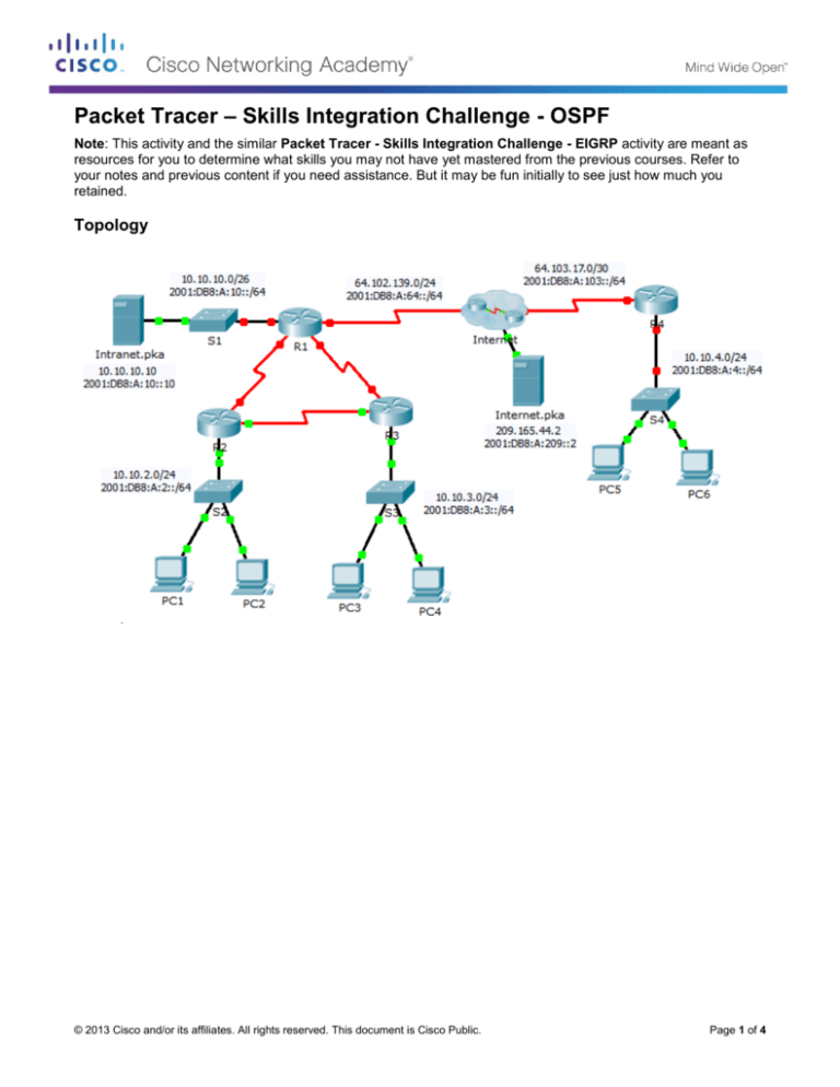
Topology
© 2013 Cisco and/or its affiliates. All rights reserved. This document is Cisco Public.
Page 1 of 4
Packet Tracer – Skills Integration Challenge - OSPF
Addressing Table
IPv4 Address
Device
Subnet Mask
Interface
Default Gateway
IPv6 Address/Prefix
10.10.10.1
255.255.255.192
N/A
G0/0
2001:DB8:A:10::1/64
64.102.139.2
N/A
255.255.255.0
N/A
S0/0/0
2001:DB8:A:64::2/64
R1
10.10.1.1
N/A
255.255.255.252
N/A
S0/0/1
2001:DB8:B:1::1/64
10.10.1.5
N/A
255.255.255.252
N/A
S0/1/0
Link-Local
2001:DB8:B:2::1/64
N/A
FE80::1
N/A
10.10.2.1
255.255.255.0
N/A
G0/0
2001:DB8:A:2::1/64
10.10.1.9
N/A
255.255.255.252
N/A
S0/0/0
R2
2001:DB8:B:3::1/64
10.10.1.2
N/A
255.255.255.252
N/A
S0/0/1
Link-Local
2001:DB8:B:1::2/64
N/A
FE80::2
N/A
10.10.3.1
255.255.255.0
N/A
G0/0
2001:DB8:A:3::1/64
10.10.1.10
N/A
255.255.255.252
N/A
S0/0/0
R3
2001:DB8:B:3::2/64
10.10.1.6
N/A
255.255.255.252
N/A
S0/0/1
Link-Local
2001:DB8:B:2::2/64
N/A
FE80::3
N/A
10.10.4.1
255.255.255.0
N/A
G0/0
2001:DB8:A:4::1/64
R4
64.103.17.2
N/A
255.255.255.252
N/A
S0/0/1
Internet
2001:DB8:A:103::2/64
N/A
Link-Local
FE80::4
N/A
NIC
209.165.44.2
255.255.255.252
© 2013 Cisco and/or its affiliates. All rights reserved. This document is Cisco Public.
209.165.44.1
Page 2 of 4
Packet Tracer – Skills Integration Challenge - OSPF
2001:DB8:A:209::2/64
10.10.10.10
Intranet
PC1 - PC6
FE80::5
255.255.255.192
10.10.10.1
NIC
2001:DB8:A:10::10/64
FE80::1
DHCP assigned
DHCP assigned
Auto Config
Auto Config
NIC
Scenario
Your business has just expanded into a different town and needs to expand its presence across the Internet.
You are tasked with completing the upgrades to the enterprise network, which includes dual-stacked IPv4 and
IPv6, and a variety of addressing and routing technologies.
Requirements
Note: Although not required, adding additional labeling to the topology may help you as you proceed. All
names and passwords are case-sensitive.
Basic Device Configuration
Configure the following on R1 and R4.
-
Set the device names to match the Addressing Table.
-
Set cisco as the encrypted privileged EXEC mode password.
-
Set a banner MOTD which includes the word warn.
-
Set the IPv4 and IPv6 addresses according to the Addressing Table.
-
Assign the link local address to each interface.
SSH
Configure SSH on R4.
-
Set a domain name of R4.
-
Create a user of admin with an encrypted password of cisco.
-
Create a 2,048-bit RSA key.
-
Configure all vty lines to use SSH and a local login.
DHCPv4
Configure R4 to act as a DHCP server for its LAN.
-
Create a DHCP pool using the name R4.
-
Assign the appropriate addressing information to the pool including the 209.165.44.2 as the DNS
server.
-
Prevent the address used by the router from being distributed to end devices.
NAT
Configure NAT/PAT on R4 so that all devices on the LAN use the IP address on the Serial 0/0/1 to
access the Internet.
-
Use a single statement in access list 1 to define the addresses that will participate in NAT. Allow only
the 10.10.4.0/24 address space.
-
Enable NAT/PAT using the access list.
-
Configure the appropriate interfaces as NAT inside or outside.
© 2013 Cisco and/or its affiliates. All rights reserved. This document is Cisco Public.
Page 3 of 4
Packet Tracer – Skills Integration Challenge - OSPF
Configure PAT on R1.
-
Use a single statement in access list 1 to define the addresses that will participate in NAT. Allow only
the 10.10.0.0/16 address space.
-
Define a pool named R1 to use all four addresses in the 64.102.139.4/30 address space.
-
Assign access list 1 to the R1 pool.
-
Configure the appropriate interfaces as NAT inside or outside.
Configure static NAT on R1 for remote access to Intranet.pka server.
-
Use a static NAT statement to redirect TCP port 80 traffic from 64.102.139.2 to 10.10.10.10.
-
Use a static NAT statement to redirect TCP port 443 traffic from 64.102.139.2 to 10.10.10.10.
Default Routing
On R1, configure an IPv4 default route using the next-hop IP address 64.102.139.1.
On R1, configure an IPv6 default route using the exit interface.
On R4, configure an IPv4 and IPv6 default route using the exit interface.
OSPF Routing
Configure OSPFv2 area 0 on R1.
-
Use process ID 1.
-
Advertise directly connected networks. Do not include the link to the Internet.
-
Prevent routing updates from being sent across the LAN interfaces.
-
Propagate the default route.
Configure OSPFv3 area 0 on R1.
-
Use process ID 1.
-
Assign 1.1.1.1 as the router ID.
-
Prevent routing updates from being sent across the LAN interfaces.
-
Complete any required OSPFv3 or IPv6 routing configurations.
Verify Connectivity
Configure PC5 and PC6 to use DHCP for IPv4 and Autoconfig for IPv6.
Verify web access to Internet.pka and Intranet.pka from each six PCs. Be sure to test both IPv4 and
IPv6. Pings are not forwarded from PC5 and PC6 to Intranet.pka.
© 2013 Cisco and/or its affiliates. All rights reserved. This document is Cisco Public.
Page 4 of 4

