Academic Plan Engineering/SolidWorks Level 1 2012-2013
advertisement
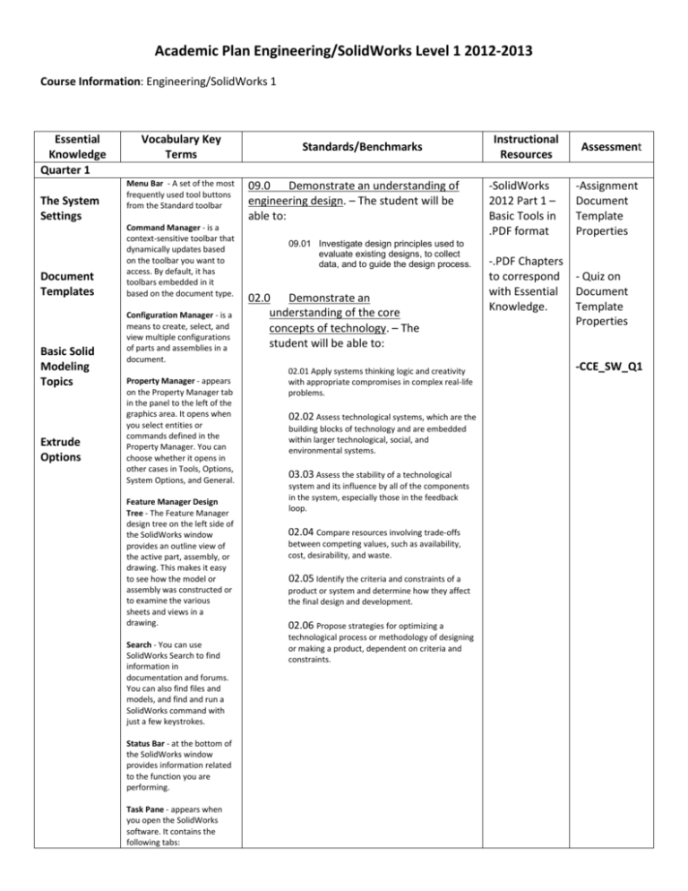
Academic Plan Engineering/SolidWorks Level 1 2012-2013 Course Information: Engineering/SolidWorks 1 Essential Knowledge Quarter 1 The System Settings Document Templates Basic Solid Modeling Topics Extrude Options Vocabulary Key Terms Menu Bar - A set of the most frequently used tool buttons from the Standard toolbar Command Manager - is a context-sensitive toolbar that dynamically updates based on the toolbar you want to access. By default, it has toolbars embedded in it based on the document type. Configuration Manager - is a means to create, select, and view multiple configurations of parts and assemblies in a document. Property Manager - appears on the Property Manager tab in the panel to the left of the graphics area. It opens when you select entities or commands defined in the Property Manager. You can choose whether it opens in other cases in Tools, Options, System Options, and General. Feature Manager Design Tree - The Feature Manager design tree on the left side of the SolidWorks window provides an outline view of the active part, assembly, or drawing. This makes it easy to see how the model or assembly was constructed or to examine the various sheets and views in a drawing. Search - You can use SolidWorks Search to find information in documentation and forums. You can also find files and models, and find and run a SolidWorks command with just a few keystrokes. Status Bar - at the bottom of the SolidWorks window provides information related to the function you are performing. Task Pane - appears when you open the SolidWorks software. It contains the following tabs: Standards/Benchmarks 09.0 Demonstrate an understanding of engineering design. – The student will be able to: 09.01 Investigate design principles used to evaluate existing designs, to collect data, and to guide the design process. 02.0 Demonstrate an understanding of the core concepts of technology. – The student will be able to: 02.01 Apply systems thinking logic and creativity with appropriate compromises in complex real-life problems. 02.02 Assess technological systems, which are the building blocks of technology and are embedded within larger technological, social, and environmental systems. 03.03 Assess the stability of a technological system and its influence by all of the components in the system, especially those in the feedback loop. 02.04 Compare resources involving trade-offs between competing values, such as availability, cost, desirability, and waste. 02.05 Identify the criteria and constraints of a product or system and determine how they affect the final design and development. 02.06 Propose strategies for optimizing a technological process or methodology of designing or making a product, dependent on criteria and constraints. Instructional Resources Assessment -SolidWorks 2012 Part 1 – Basic Tools in .PDF format -Assignment Document Template Properties -.PDF Chapters to correspond - Quiz on with Essential Document Knowledge. Template Properties -CCE_SW_Q1 Toolbars - are available for most SolidWorks tools, and also for add-in products. Named toolbars assist you in performing specific design tasks such as applying surfaces or drawing curves. Quarter 2 Extrude and Revolve Revolve Parts – Ball Joint Arm Derived Sketches – Center Ball Joint 3D Drawing Exercises Extrude Features - defines the characteristics of extruded features. You can create these types of extruded features: Solid or Thin, Boss/base, Cut, surface. Revolve - add or remove material by revolving one or more profiles around a centerline. You can create revolved boss/bases, revolved cuts, or revolved surfaces. The revolve feature can be a solid, a thin feature, or a surface. Derived Sketches - A copy of a sketch, in either the same part or the same assembly that is connected to the original sketch. Changes in the original sketch are reflected in the derived sketch. Sketch - A collection of lines and other 2D objects on a plane or face that forms the basis for a feature such as a base or a boss. 09.02 Examine the influence of personal characteristics, such as creativity, resourcefulness, and the ability to visualize and think abstractly on the Engineering Design process. 08.0 Demonstrate an understanding of the attributes of design. – The student will be able to: 08.01 Apply the design process; including defining a problem, brainstorming, researching and generating ideas, identifying criteria and specifying constraints, exploring possibilities, selecting an approach, developing a design proposal, making a model or prototype, testing and evaluating the design using specifications, refining the design, creating or making it, and communicating processes and results. - Quiz on -.PDF Chapters Extrude vs. to correspond Revolve with Essential -Assignment Knowledge. .PDF _____ - Quiz .PDF Chapter Review Questions for 4,5,6 -CCE_SW_Q2 08.02 Translate design problems that are seldom presented in a clearly defined form. 08.03Evaluate a design continually, and improve and revise the idea of the design as needed. 08.04. Evaluate factors taken into account in the process of engineering. 3D Sketch - A 3D sketch is non-planar and can be used to guide a sweep or loft, for example. Quarter 3 Rib & Shell Features – Formed Tray Linear Patterns –Test Tray Circular Shell - A feature that hollows out a part, leaving open the selected faces and thin walls on the remaining faces. A hollow part is created when no faces are selected to be open. Patterns - A pattern repeats selected sketch entities, features, or components in an array, which can be linear, circular, or sketch-driven. If 09.03 Construct a prototype or a working model used to test a design concept by making actual observations and necessary adjustments. -Assignment -.PDF Chapters ________ to correspond with Essential - Quiz .PDF Chapter Knowledge. Review Questions for ______ Patterns – Spur Gear the seed entity is changed, the other instances in the pattern update. 09.04 Evaluate factors taken into account in the process of engineering. Quarter 4 Bottom Up Assembly – Link Assembly Drawing Preparations Assembly Drawings – Links assembly Sheet Metal Drawings – Post Cap 2D to 3D – Convert AutoCAD into SolidWorks Bottom up Design - An assembly modeling technique where you create parts and then insert them into an assembly. Link Assembly - You can link the value of a document property, a custom property, or a configuration-specific property to the text of a note. You can also link a property to rows of a table or BOM. If the value of the property changes, the linked text changes automatically. Drawing - A 2D representation of a 3D part or assembly. The extension for a SolidWorks drawing file name is .SLDDRW. 09.05 Evaluate factors taken into account in the process of engineering. 11.0Demonstrate the abilities to apply the design process. – The student will be able to: 11.01 Interpret the design problem to solve and decide whether or not to address it. 11.02 Evaluate criteria and constraints and determine how these will affect the design process. 11.03 Refine a design by using prototypes and modeling to ensure quality, efficiency, and productivity of the final product. 11.04 Evaluate the design solution using conceptual, physical, and mathematical models at various intervals of the design process in order to check for proper design and to note areas where improvements are needed. 11.05 Produce a product or system using a design process. 11.06 Evaluate final solutions and communicate observations, processes, and results of the entire design process, using verbal, graphic, quantitative, virtual, and written means, in addition to three-dimensional models. -CCE_SW_Q3 -Assignment -.PDF Chapters ________ to correspond with Essential - Quiz .PDF Chapter Knowledge. Review Questions for ______ -CCE_SW_Q4
